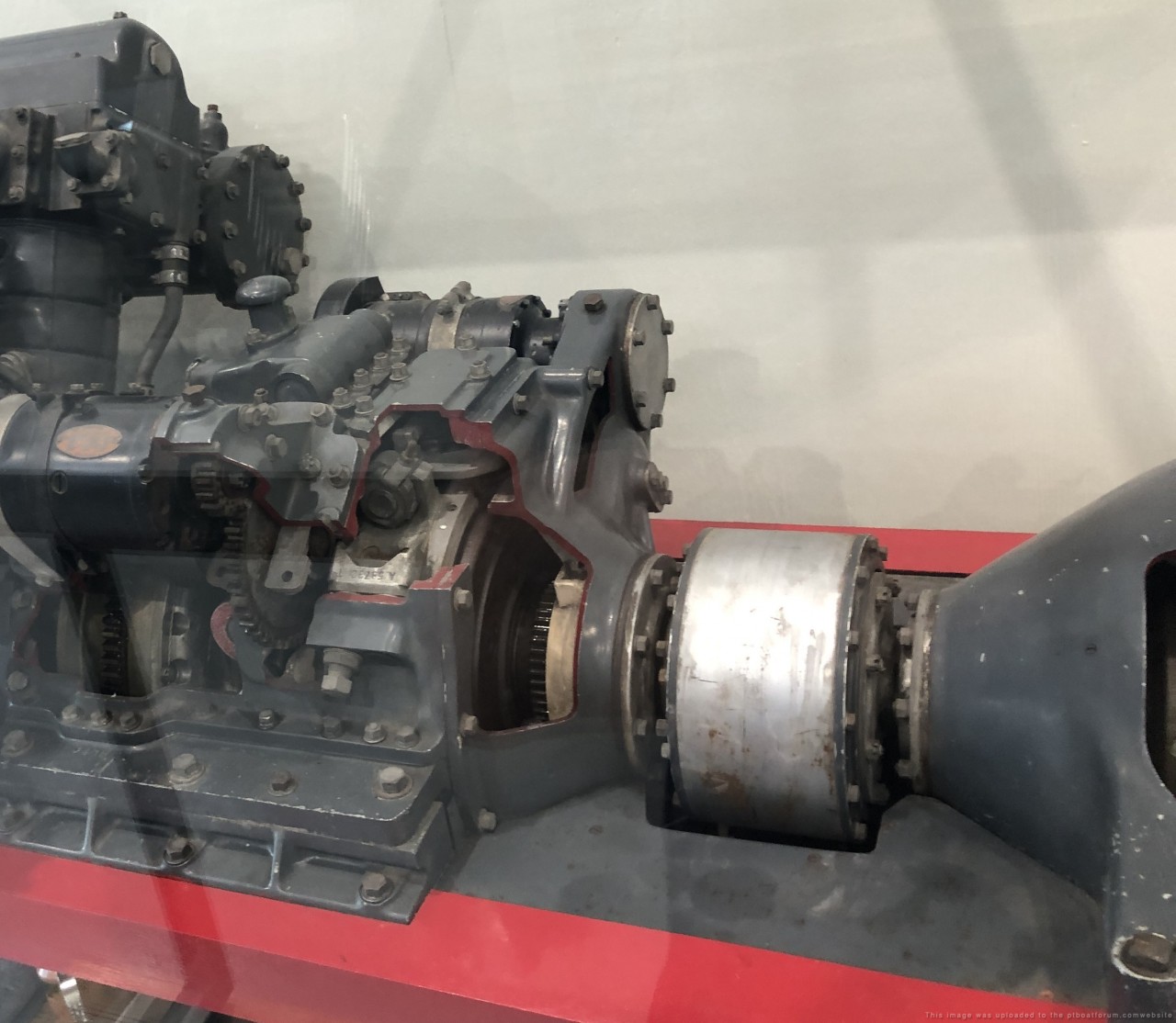
Hey there shipmates! I am touring the PT305 in New Orleans and came across a motorized rotating cutaway Packard 4M-2500 engine display. It is really interesting but raised a new question. Attached to the output shaft of the Joes Gears Transmission (F-N-R) was a new type of flexible coupling and some sort of gear unit (a reducer or something?) that I have never seen before. I asked a few of the guys at the museum and they did not know either. It looks like it has a 1:1 input /output speed and I cannot find any labels or nametags on it. I have seen an Elco Vee Drive before and it is not a Vee Drive. So my question is..... what is this thing and what does is its function? Hopefully somebody out there will know. I am asking for a friend....
Thanks Jerry
Transmission cutaway engine and Silver Flexible Coupling with gear unit at right
Cutaway gear unit
Jerry Gilmartin
PT658 Crewman
Portland OR
Posted By: Jerry Gilmartin | Posted on: Mar 13, 2024 - 12:12am
Total Posts: 1486 | Joined: Oct 8, 2006 - 11:16pm
Jerry I really don't know what that is , but it reminds me of a power take off on a tractor , could it help with transferring the power to the props? Regards
Scott Campbell 2nd gen,PT 248
Ron 20
Posted By: Scott C | Posted on: Mar 15, 2024 - 1:30pm
Total Posts: 114 | Joined: Nov 20, 2019 - 4:34pm
PTO? OK thanks Scott! I will look into that. Appreciate the suggestion!
Jerry Gilmartin
PT658 Crewman
Portland OR
Posted By: Jerry Gilmartin | Posted on: Mar 15, 2024 - 5:26pm
Total Posts: 1486 | Joined: Oct 8, 2006 - 11:16pm
Jerry,
Interesting, but I do not think the coupling and gear box are PT boat related. As you know from PT 658, coming out of the transmission, PT boats were a direct drive. Other craft, such as ASRs, utilized Packard engines. As mention earlier it does look like a PTO for anther mechanism. Hard to tell, would need to research some more.
Bill Smallshaw
Posted By: smallwi | Posted on: Mar 15, 2024 - 7:06pm
Total Posts: 141 | Joined: Jun 21, 2007 - 3:02pm
Welcome to the Sunday morning world of the retired mechanical engineer! That should be taken as a warning.
Studying this picture and another one I found online of the same unit taken from a different angle, I believe this is a variation of an epicyclic gear set that provides an output speed higher than the input speed. I have no idea what its application would be, and as others have stated, itŌĆÖs unlikely to be a PT boat application. Is there a maritime use where youŌĆÖd want the propeller turning even faster than the Packard engine?
I made a drawing of how the gears interact, but the Upload Images button isn't appearing next to the box where I'm typing the reply. Without the drawing an explanation of how it works is rather difficult. The best I can do is to point out that the large gear on the right is fixed to the transmission housing - it does not rotate. The small gears in the center are attached to a shaft that runs through the center of the large gear on the right - this is the output shaft. The output shaft does not connect to the large gear on the right, it just passes through the center, and remember that the large gear on the right doesn't move at all. You can't actually see the output shaft passing through the large gear, but it has to be there for this unit to do anything at all. When the large gear on the left is turned by the input shaft from the engine, it turns the small gears in the center. There are at least three of the small gears and possibly four, and all are attached to the output shaft. When the small gears push against the stationary gear on the right, that makes the whole set of small gears and their output shaft turn in the same direction as the large gear on the left. Because of the smaller size of the gears in the center relative to the two gears on either side, the small gear assembly and output shaft turn faster than the input shaft. The actual speed ratio depends on the number of teeth on the large and small gears, but based on what can be seen IŌĆÖd say itŌĆÖs around a two to one speed increase.
IŌĆÖve never before seen an epicyclic gear set using bevel gears, but it makes sense in a high horsepower application like this. ThatŌĆÖs because spur gears in a typical epicyclic gear set engage one gear tooth at a time and the input gear is much smaller than the other gears. These two factors make it prone to failure. This bevel gear arrangement provides an input gear thatŌĆÖs just as big and beefy as the rest of the gear set and the large gears on either side have four teeth engaged with the small gears at all times. Distributing high power through multiple gear teeth at the same time is the key to success. Keep in mind that the JoeŌĆÖs gear box behind the Packard engine (if I understand it correctly) does not change the output speed relative to the input speed, itŌĆÖs either in gear (forward or reverse) or in neutral. There are no spur gears increasing or decreasing the speed, and the spur gears used to create a reverse rotation aren't going to see full engine power. Some maritime application apparently needed shaft speed multiplication, and this was the answer that could handle around 2,000 horsepower. It just wasn't a PT boat. A more logical application might be an industrial engine driving a pump or generator that needs to turn faster than the engine, and that might be the original use of this unit. The Hall-Scott Defender V12 was used in such industrial applications, particularly large irrigation pumps, but I donŌĆÖt think transmissions like this were used. Also, if you fed the power into the other end of this transmission, it would reduce the speed - it works in either direction.
Randy McConnell (Randall J. McConnell III)
Posted By: PRJM3 | Posted on: Mar 17, 2024 - 11:21am
Total Posts: 95 | Joined: May 25, 2009 - 2:47pm
Thanks Randy!
This explanation helps a lot! I also think this was never installed on a PT boat. One bonus is that it is a moving exhibit, with a motor that spins around the entire works! I took a video of it in action and will try to both post it here and send you an email so you can watch how it moves. It is super interesting to see all the internal gears & etc. moving! One thing that was pointed out to me is that the output shaft speed appears to be exactly the same as the input speed. Confusing. But that is just looking with the naked eye and not using any sort of tach. The little motor can only spin the assembly around at 10-15 rpm so if there is a speed difference, it may not be as apparent at such low speeds. OK so give me some time and I will try to post that video asap.
Thanks all of you for your help!
Jerry Gilmartin
PT658 Crewman
Portland OR
Posted By: Jerry Gilmartin | Posted on: Mar 17, 2024 - 12:36pm
Total Posts: 1486 | Joined: Oct 8, 2006 - 11:16pm
Jerry,
I look forward to seeing the video. That should verify my conclusion about which parts move and which stay stationary - or not! Calculating speed changes with epicyclic gears isn't as straight forward as with spur gears, so I might have it totally wrong. But if it doesn't change the speed of the output or reverse its direction, what's the point? It's not a power take off because a PTO has one input drive and two or more output drives. It takes power off a main drive and directs it somewhere else.
I love those motorizes displays. Maybe they tacked it onto the back end of a Packard just because it's fun to watch.
Randy McConnell (Randall J. McConnell III)
Posted By: PRJM3 | Posted on: Mar 17, 2024 - 2:55pm
Total Posts: 95 | Joined: May 25, 2009 - 2:47pm
This is a very interesting question. While I can see a M 2500 used for an industrial purpose, I would think tat is would not have been a very economic, nor practical choice.
That said, what else would want to benefit from the HP and at the same time increase the output RPM's. What else used Packards? How about hydroplanes. They certainly fit the needs, but I have never spent any time around one to examine the drive train.
Posted By: JEno | Posted on: Mar 18, 2024 - 3:48pm
Total Posts: 75 | Joined: Oct 13, 2019 - 9:52am
The Hydroplane boats used Packard Merlin and a few Griffin airplane engines, totally different engines!
Posted By: Stearman | Posted on: Mar 18, 2024 - 9:18pm
Total Posts: 151 | Joined: Nov 1, 2017 - 9:38pm
Good News! I just uploaded the video to YouTube. Here is the link to watch the video. Let me know what you think!
Jerry
Click on link to see video of cutaway Packard Engine in operation
[url]https://youtu.be/LJlH_f8kEP8[/url]
[red][b]Jerry: The Video has been embedded into this post and on a new post found on the second page of this post.[/b][/red]
Jerry Gilmartin
PT658 Crewman
Portland OR
Posted By: Jerry Gilmartin | Posted on: Mar 18, 2024 - 10:51pm
Total Posts: 1486 | Joined: Oct 8, 2006 - 11:16pm
Jerry,
Excellent video! It verifies that the large gear on the right is stationary, and the gearbox is therefore operating as an epicyclic geartrain. You can also see that there is speed multiplication occurring but instead of increasing the speed of the output shaft, as I thought would happen, it is actually reducing the speed of the output shaft relative to the input shaft. In the video, rather than watching the output and input shafts on either end of the transmission, which are only both visible at the same time for a second or two, it's better to watch the gears inside the transmission around the 2:40 mark of the video. There are shiny silver rectangular portions of the output shaft visible between the small gears in the center of the transmission. If you watch those silver rectangles move relative to the large gear immediately to the left of them, you can see that the rectangles are rotating slower than the large gear. Focus on the silver rectangles and try to ignore the small gears that are turning. The speed difference is particularly noticeable with the silver rectangle that has a lot of oil staining on it. Epicyclic gear trains are rather confusing, and I obviously got the multiplication factor totally wrong. I'm not going to try to figure out why it's under-driving the output shaft rather than over-driving it, that probably has something to do with both large gears affecting the output shaft. Likewise, I don't think we'll know what the under-drive ratio is; I'm good with just knowing the output shaft is under-driven!
If this setup was used in some boat, it makes more sense that the propeller is turning slower than the engine. Gasoline engines like the Packard are considered to be "high speed" engines, with diesel and steam engines generally being "low speed". (There are a few high speed diesels.) To my knowledge, propellers, both aircraft and marine, lose efficiency when turned as fast as high speed gasoline engines, and a direct-drive gasoline aircraft engine is pretty rare. Virtually all of the gas aircraft engines have gear reductions in their nose cases to keep the propellers in an acceptable speed range. That said, the PT Boats were obviously capable of operating in a broad speed range with three direct drive Packards. (My Dad had stories about using undersized props, but that would be off topic here.) Perhaps there was a Packard powered boat that needed the gear reduction, possibly because it had a lower power to wieght ratio (i.e, less horsepower available for the relative weight of the boat). Would some of the crash boats, which I believe had two Packard engines, fall into that category?
Randy McConnell (Randall J. McConnell III)
Posted By: PRJM3 | Posted on: Mar 19, 2024 - 10:51am
Total Posts: 95 | Joined: May 25, 2009 - 2:47pm
Stearman,
I stand corrected.
Great video, but if I am not mistaken, don't read my last post, LOL, that add-on unit appears to reduce the output RPM, no?
Posted By: JEno | Posted on: Mar 19, 2024 - 11:06am
Total Posts: 75 | Joined: Oct 13, 2019 - 9:52am
Posted By: Dick | Posted on: Mar 19, 2024 - 11:38am
Total Posts: 1487 | Joined: Aug 27, 2006 - 6:36pm
Thanks Randy! Thanks also to Dick for embedding the video into the thread.
Randy yes I think your explanation makes a lot of sense. maybe the crash boats had these? That way the engine speed could be high and the prop speed slower than that on a PT boat. We need some Crash boat experts to answer the new question if they had this epicyclic speed reducer installed on their crash boats.
Jerry Gilmartin
PT658 Crewman
Portland OR
Posted By: Jerry Gilmartin | Posted on: Mar 19, 2024 - 2:52pm
Total Posts: 1486 | Joined: Oct 8, 2006 - 11:16pm
Hey Good News!
I came across a booklet called Development of Packard marine Engine during WW2(September 1938 to April 1945) by Marsden Ware Head of Marine Engine Development. In this booklet he explains what this gear is for. Its official name is the Packard Bevel Pinion 2:1 Reduction Gear BP-1. It was designed in response to a request from the US Army to place inside their 104' Air Sea Rescue Boats.
Here is the transcript of the explanation given in the book on pages 12 and 13
2:1 Reduction Gear for the 4M-2500 engine (Reduction Gear Model BP-1)
The Army, in adapting the 4M-2500 engine to the 104ŌĆÖ Air-Sea Boat, desired to have a 2:1 reduction gear. The design of the boat was such that a reduction gear should provide a more efficient result. Being unable to obtain a suitable reduction gear of sufficient capacity from other sources, they requested us to design and build a suitable unit and this resulted in Packard gear BP-1. This uses bevel planetary type gears with four pinions mounted on the output shaft. Gleason Zerol type of gearing was specified.
Layouts on this were started in October of 1942, and detailing started November 6. The first production unit was shipped April 3, 1943. A total of 440 have been built to date. A photograph of this unit is shown in Appendix H.
While this gear was designed specifically for the 104ŌĆÖ boat, it is interesting to note that it had other uses. Some of the early gears were shipped abroad for purposes which have never been disclosed to us. Approximately thirty have been used in so-called ŌĆ£sea mulesŌĆØ which are used as tugs and for moving barges, etc., in harbor work. The original sea mules were engineered largely by Chrysler. Some of the later larger units have been equipped with Hercules diesel engines and the Packard gear. With a 6:1 reduction in the Hercules engine, the overall reduction with the Packard gear becomes 12:1. These units were tested late in the fall of 1944, and showed satisfactory results on tests, but we do not have much information on actual service experience.
Here is the photo from the aforementioned Appendix H
Posted By: Jerry Gilmartin | Posted on: Apr 16, 2024 - 11:44pm
Total Posts: 1486 | Joined: Oct 8, 2006 - 11:16pm
Great work! You letting the museum know?
Posted By: Andy Small | Posted on: Apr 17, 2024 - 5:06am
Total Posts: 266 | Joined: Nov 20, 2013 - 9:04pm
Yes I will be sending it over today.
Jerry Gilmartin
PT658 Crewman
Portland OR
Posted By: Jerry Gilmartin | Posted on: Apr 17, 2024 - 10:15am
Total Posts: 1486 | Joined: Oct 8, 2006 - 11:16pm
Great research find!!! Well done. I had spoken with Mr. Ruth at U.S. Crash Boats. We had a long discussion, but he had never heard of such a unit. I would think that he would be interested. May I copy and forward the posted information to him?
Posted By: JEno | Posted on: Apr 19, 2024 - 4:52am
Total Posts: 75 | Joined: Oct 13, 2019 - 9:52am
Hello JEno
Yes that is fine with me. I wrote an email to them 2 weeks ago and have not heard back from their group yet. [:-cheers-:][:-cheers-:]
Jerry Gilmartin
PT658 Crewman
Portland OR
Posted By: Jerry Gilmartin | Posted on: Apr 20, 2024 - 8:10pm
Total Posts: 1486 | Joined: Oct 8, 2006 - 11:16pm
Great find, Jerry, and mystery solved! I found another reduction gearbox that was used in Air Sea Rescue boats, but it was an angle drive or V-drive used in the 85-foot boats. Working from memory, it was something like a 1.5 to 1 reduction unit and used bevel spur gears. As the 85-foot boat used two Packard engines versus the three in a PT boat, the reduction gearing falls in line with my thinking that they were "geared down" for the reduced power-to-weight ratio. The 104-foot boat would fall into the same category. I found that information on the uscrashboats.org site, including schematic drawings of the reduction gear box used in the 85-foot boats. I did not find anything on that site for the 104-foot boats but may have missed something.
Randy McConnell (Randall J. McConnell III)
Posted By: PRJM3 | Posted on: Apr 23, 2024 - 9:58am
Total Posts: 95 | Joined: May 25, 2009 - 2:47pm