The PT Boat Forum
http://www.ptboatforum.com/cgi-bin/MB2/netboard.cgi
» Forum Category: PT Boats of WWII
http://www.ptboatforum.com/cgi-bin/MB2/netboard.cgi?cid=101&fct=showf
» Forum Name: PT Boats - General
http://www.ptboatforum.com/cgi-bin/MB2/netboard.cgi?fct=gotoforum&cid=101&fid=102
» Topic:
REPLICA 80 foot ELCO UNDER CONSTRUCTION
http://www.ptboatforum.com/cgi-bin/MB2/netboardr.cgi?cid=101&fid=102&tid=4343
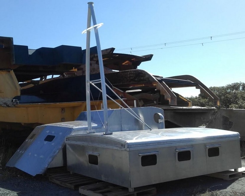
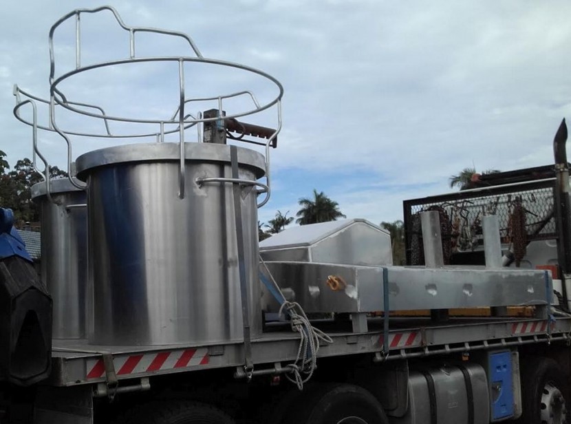
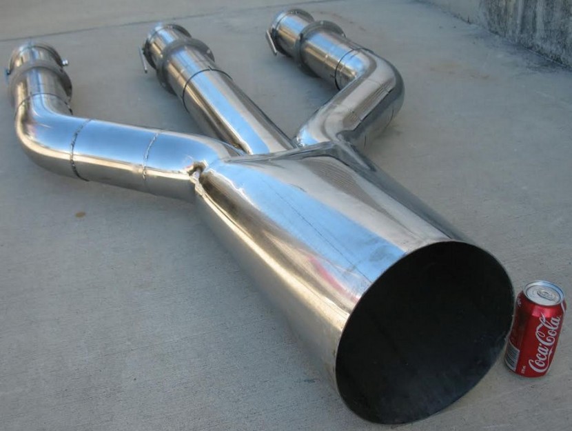
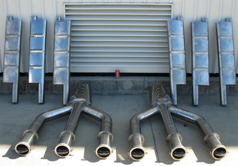
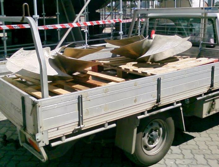
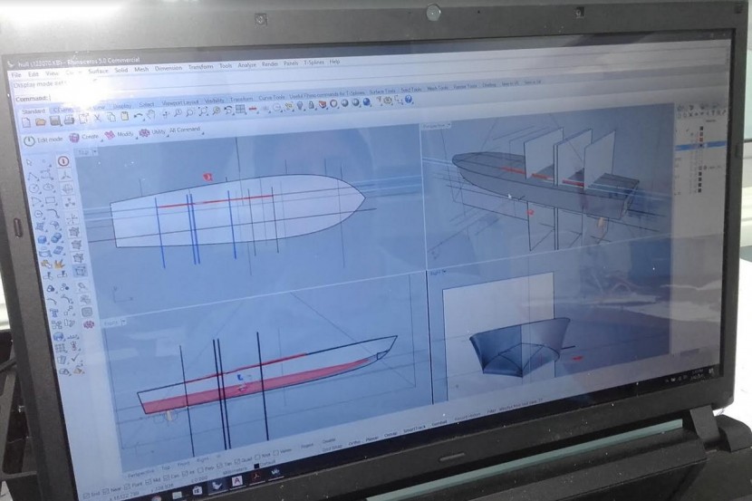
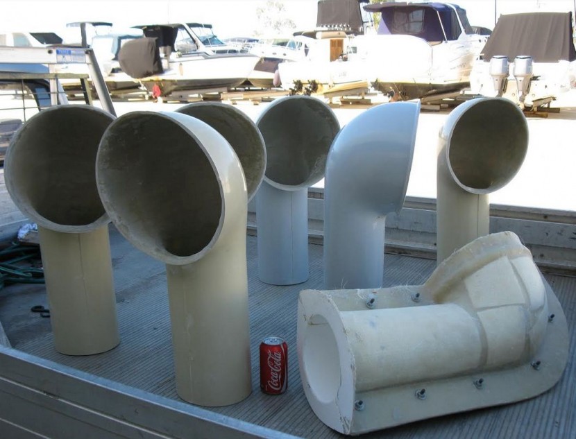
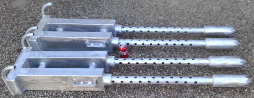
For the last few years a gentleman from Down Under, Paul McCamley, has been quietly building a replica of PT 109 at his home. Mostly by himself. When he first contacted me I was skeptical but he has since amazed me with his resolve and ability to get things done. Here is a message from Paul and some photos of his progress:
[green]Paul McCamley, retired auto mechanic in Brisbane Australia, grew up with admiration for the greatest American President in my lifetime.....John Fitzgerald Kennedy.
Sadly, 22 November, 1963 saw this great era in the USA come to a tragic end.
I believe Australia owes it's freedom to the many, many Americans who sacrificed so much in WW2.
The construction of this vessel is a tribute not just to JFK, but to all those brave men and women of the American Military.
Please, always stand for the flag.
Pension checks don't stretch far, but the ELCO 109 project started late 2014, regardless.
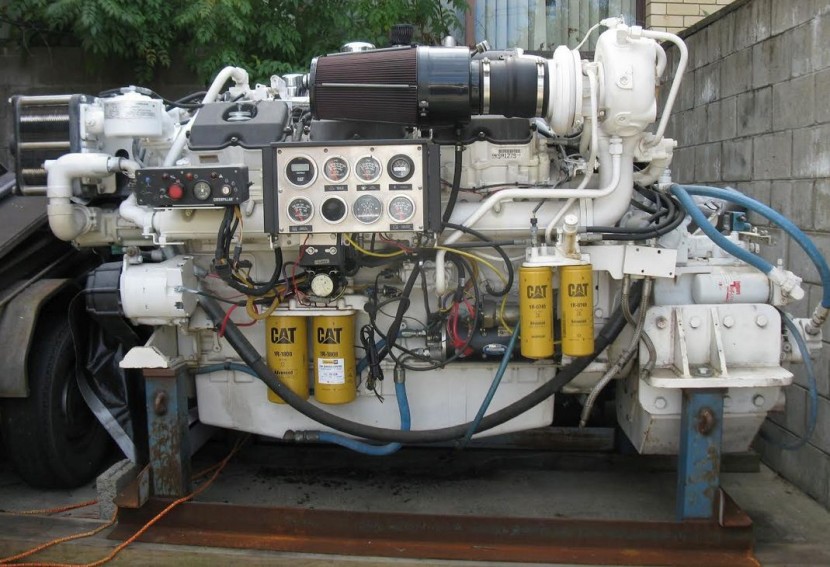
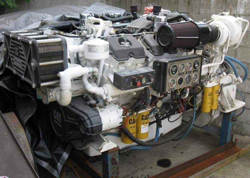
Two Caterpillar 3412e V12 twin turbo 1500hp marine power plants with twin Disc 5202sc gearboxes purchased.
Budget considerations require all components to be sourced / fabricated before the hull can be started.
All components are now ready for hull CAD / CAM fabrication to begin.
Trying to build a replica vessel by one retired mechanic that initially required the resources and budget of the United States Navy and teams of hundreds of skilled craftsmen is a daunting challenge.
Jeff Davidson and David Waples have been the guiding inspiration in this project.
There are thousands of design and engineering challenges in this build.
I hope I am up to the challenge.
I do not want to die wondering.
Warmest regards,
Paul McCamley[/green]

Posted By: Jeff D | Posted on: Jan 27, 2018 - 6:23am
Total Posts: 2203 | Joined: Dec 21, 2006 - 1:30am
That is a very ambitious project and I wish the gentleman great success. One thought about his choice of building materials, the use of what appears to be stainless steel for large components will add much additional topside weight.
Larry
62 Bel-Air
260 Eagle EXP
79 Cole TR-2
2016 Corvette Z51
Posted By: bubbletop409 | Posted on: Jan 27, 2018 - 10:42am
Total Posts: 164 | Joined: Apr 22, 2013 - 11:48pm
It's aluminum except for the exhaust which is indeed stainless so it should be OK.
Posted By: Jeff D | Posted on: Jan 27, 2018 - 12:16pm
Total Posts: 2203 | Joined: Dec 21, 2006 - 1:30am
One man with a dream can move a mountain! Best wishes to Mr McCamley in this endeavor.
Rick Schaefer
Splinter PT 63 108
TM2c John E Mirus
Solomon Islands
Dec 43 - Jan 45
Posted By: rickas | Posted on: Jan 27, 2018 - 1:27pm
Total Posts: | Joined: Unregistered
Wow, just wow! How many of us have had this dream, and now, here is a man living the dream. My hats off to him!
Posted By: Stearman | Posted on: Jan 27, 2018 - 8:34pm
Total Posts: 151 | Joined: Nov 1, 2017 - 9:38pm
Bravo Zulu !! and all aluminum too! WOW!
Good Luck and keep charging!
TED
Posted By: TED WALTHER | Posted on: Jan 29, 2018 - 6:11am
Total Posts: 3091 | Joined: Oct 16, 2006 - 7:42am
Such an undertaking. It just proves that when you believe in something so strongly it can be done. From what I see so far, this looks really awesome. Aluminum components how great is that. All the best sir in this project of love.
Posted By: Frank Andruss | Posted on: Jan 31, 2018 - 6:50am
Total Posts: 3964 | Joined: Feb 9, 2007 - 11:41am
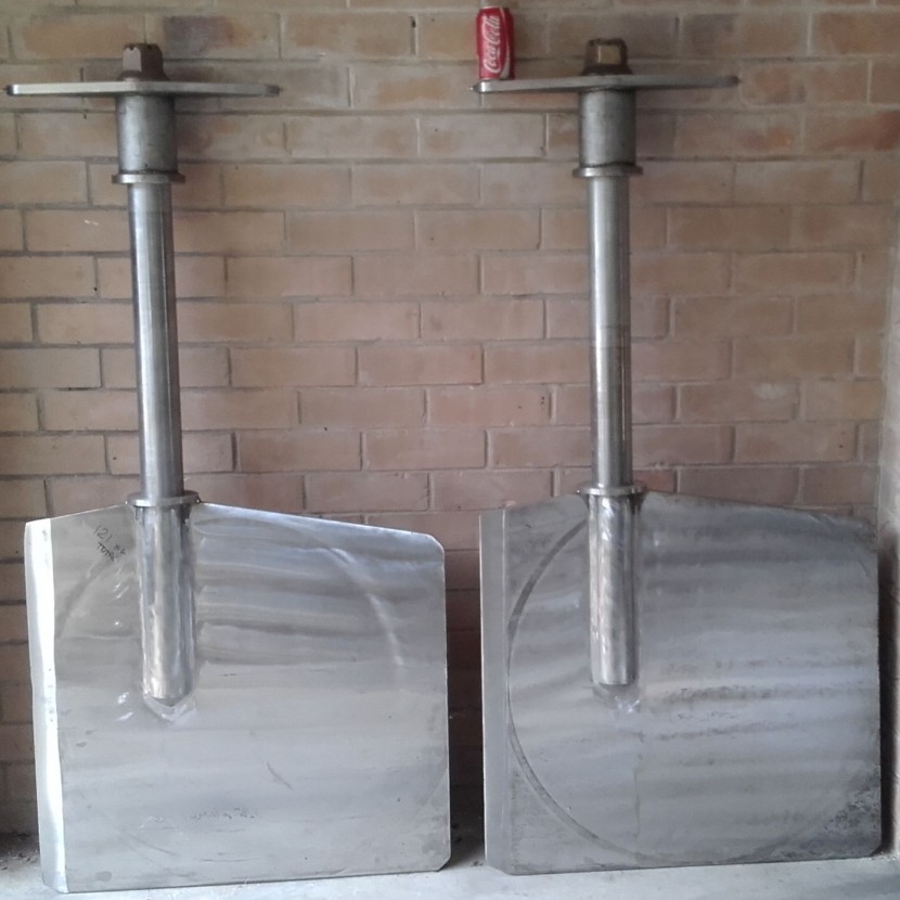
Interesting looking propellers.
Charlie
Posted By: 29navy | Posted on: Jan 31, 2018 - 8:55am
Total Posts: 611 | Joined: Dec 28, 2006 - 3:02pm
Those are high surface high speed props for sure!
Former crew member of the Big Blue Sightseer ex-PT 486
Posted By: mcgovern61 | Posted on: Jan 31, 2018 - 12:56pm
Total Posts: | Joined: Unregistered
Looks great! Good luck, Mr. McCamley...
Posted By: Drew Cook | Posted on: Jan 31, 2018 - 4:25pm
Total Posts: 1306 | Joined: Oct 19, 2006 - 10:44am
Some more photos of what Paul calls his "1:1 scale model".
Paul rigged up a lathe to carve the plug for the 20mm base mold, unfortunately he didn't send a pic of himself covered head to toe in green foam dust after a carving session:
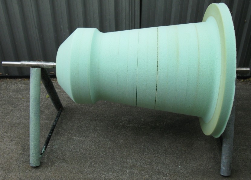
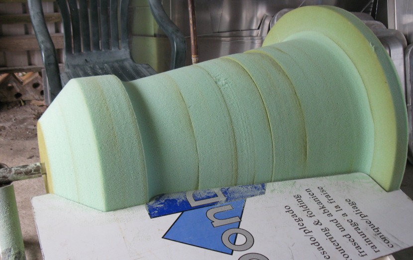
The results:
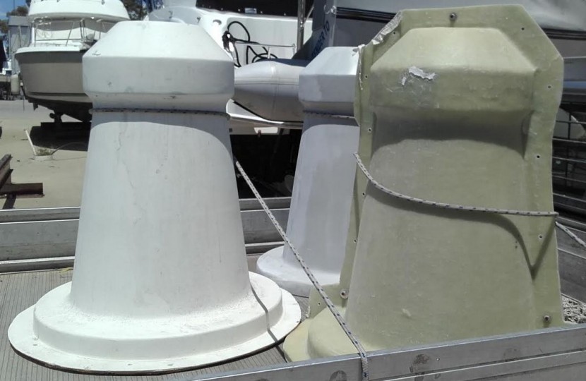
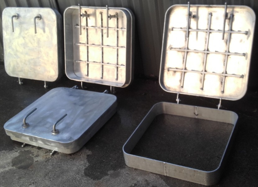
Deck Hatches:
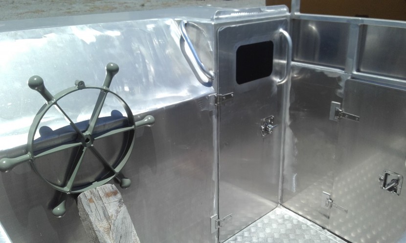
Helm:
Rudders:
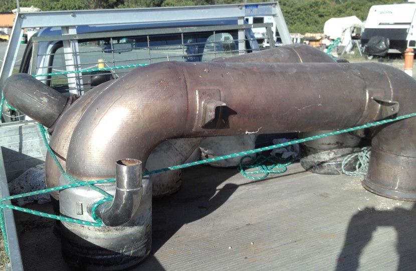
Exhaust pipes:
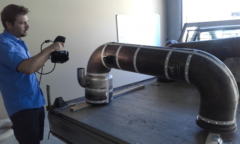
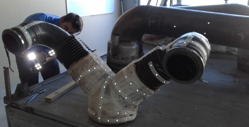
Exhaust pipes being 3D scanned for use in hull design:
Posted By: Jeff D | Posted on: Feb 9, 2018 - 7:31am
Total Posts: 2203 | Joined: Dec 21, 2006 - 1:30am
Impressive!
Former crew member of the Big Blue Sightseer ex-PT 486
Posted By: mcgovern61 | Posted on: Feb 9, 2018 - 8:01am
Total Posts: | Joined: Unregistered
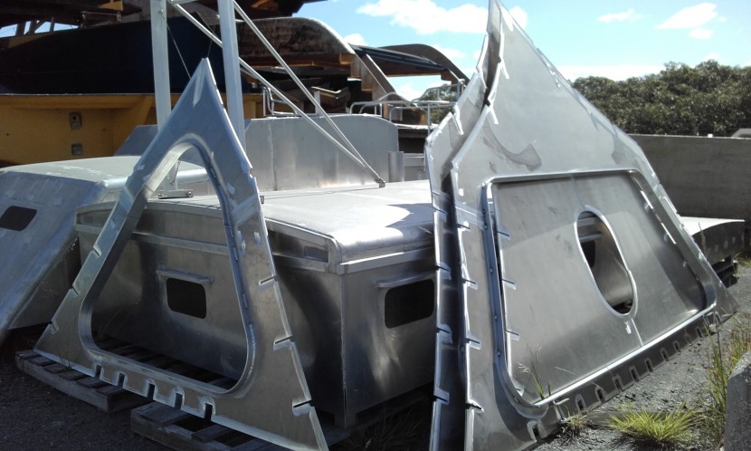
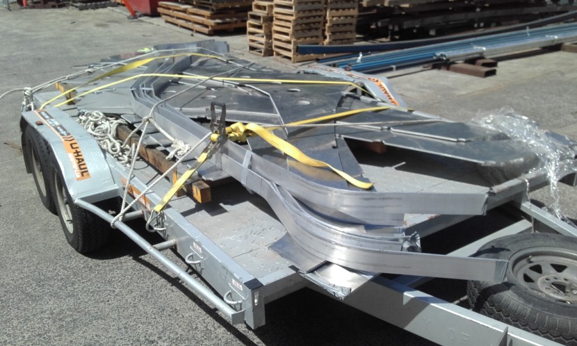
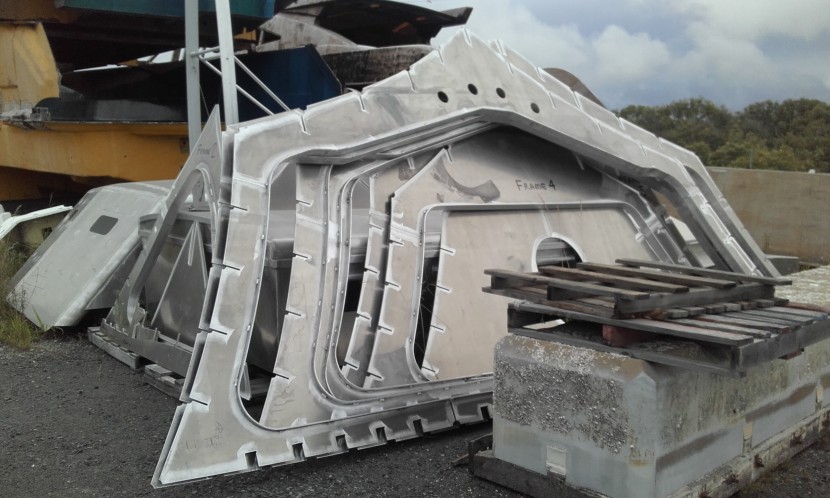
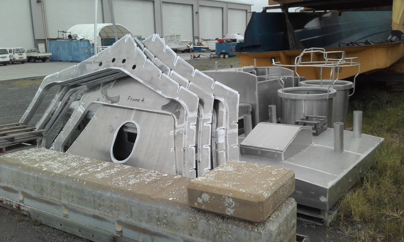
Paul has been busy and sent me this update on what he calls his 1:1 scale model. Very impressive, thank you Paul!
[green]Hi Jeff.
1959 Cadillac.........
Here are the latest photos of Project 109 progress.
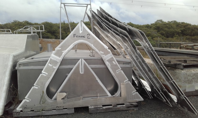
Frames 6-11.
Only 30 more to go!
(better get used to eating SPAM)
The beam on an ELCO 80' is 2 feet wider than the length of a 1959 Cadillac!
(they tell me the Cadillac is 225 inches)
This is a big scale model boat.
I have chosen Caterpillar V12 twin turbo engines over brushless electric motors.
(scale speed)
Please feel free to post the latest photos as you wish.
( would be great click bait with the heading '1959 CADILLAC' )
Jeff, I don't have to tell you that DNV certified marine grade 5083 aluminium is expensive.
That's just the sheet aluminium.
Not counting the CAD/CAM, cutting, shipping, welding / fabrication.
My small brain is hurting.
You are a numbers man Jeff.
Hey, try these exercises.
I would be very interested to have your input on local USA pricing.
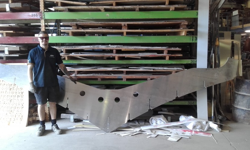
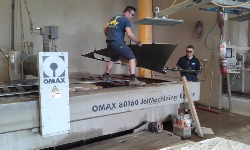
1) There are 500 triangle re-enforcing gusset plates 300mm x 300mm
5083 marine grade DNV certified aluminium - 10mm thick material.
(that's 12 inches x 12 inches in the old money)
Kindly research a local supplier costing.
(be sitting down)
2) FRAMES - 5083 marine grade DNV certified x 10mm thick sheets.
Size - 1.83m x 6.10m (that's 6 foot x 20 feet in the old money)
50 x sheets required
That's JUST the frames!
3) FRAME RIDERS (the re-enforcing bands around the internal void on each frame).
Material - 6082 aluminium flat bar - 100mm x 10mm thickness
600 meters required (yes, that IS 600 meters)..........................$.............. ?
(just the accurate folding / bending of these 6-11 frame rider bars had lots of zeros in the invoice)
You can put these questions, or even the whole e-mail on the Forum for comment.
Be interested in the replies.
Stay safe over xmas Jeff and family.
2019 is going to be one hell of a year.
Warmest regards,
Paul.
(model boat builder, scale 1:1)[/green]
Posted By: Jeff D | Posted on: Dec 18, 2018 - 3:13am
Total Posts: 2203 | Joined: Dec 21, 2006 - 1:30am
Holy cow, and I thought some of my PT building projects were ambitious.
Larry
62 Bel-Air
260 Eagle EXP
79 Cole TR-2
2016 Corvette Z51
Posted By: bubbletop409 | Posted on: Dec 18, 2018 - 10:22am
Total Posts: 164 | Joined: Apr 22, 2013 - 11:48pm
Simply amazing....
Will
Posted By: Will Day | Posted on: Dec 23, 2018 - 4:48pm
Total Posts: | Joined: Unregistered
Jeff, have you received any updates recently?
Former crew member of the Big Blue Sightseer ex-PT 486
Posted By: Gerry McGovern | Posted on: Dec 6, 2019 - 6:51am
Total Posts: 81 | Joined: Oct 7, 2016 - 1:47pm
Hi Gerry, I heard from him November 11th he is still going strong!:
[green]All the frame CAD files done.
Lotta engineering decisions to consider.
Last one the transom.
(the dimensions in the attached pic look ok to you ?)
Next stage nesting to suit 2.0m x 9.0m sheets, prior to water jet cutting.
THEN, obtaining quotes out of China.
And freight, and customs, and import tax, and local tax, and delivery.
THEN, fabrication, waterjetting, welding, riders, storage.
Not going to get much change out of $100,000.
That's modelling.
Always takes longer than estimated, and costs more than is sensible[/green]
And November 14th:
[green]Presently on task for transom build.
This entails all the exhaust components - transom pipes, mufflers, bracketing
combined to a trial fit up.
Much more engineering involved than in a 1/35 scale build !
(all SS 316 components must be electrically isolated from aluminium hull - other wise you are making a battery. Galvanic corrosion BIG TIME ! )
(so, many insulators and extra bracketing involved)
Also $$$$ involved in fuel delivery systems.
I have spent thousands of dollars on 316 fuel plumbing components.
Fuel load........4000 liters.
Cat twin turbo V12's chew 297 Liters / hour each @ WOT)
Also working on internal exhaust system.
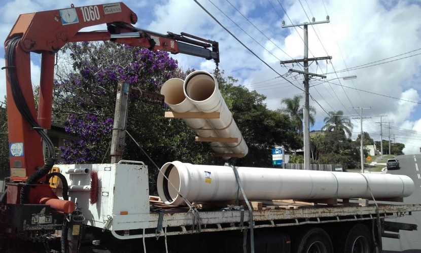
2 off, 8.0 meters of passivated SS 316 tubing
@ 254mm diameter (10 inch in the old money)
Photo of custom made exhaust coupling rings (316)
Shaft stern tubes (150mm diameter - 6 inch in the old money)
Shaft seals are $2,600 each (2 x required)[/green]
Posted By: Jeff D | Posted on: Dec 6, 2019 - 8:38am
Total Posts: 2203 | Joined: Dec 21, 2006 - 1:30am
Looking like he's gonna make a good shot at the boat. Best of luck. keep us posted
[:-cheers-:]
Bill P Reese
Posted By: billpr | Posted on: Dec 8, 2019 - 3:09pm
Total Posts: | Joined: Unregistered
Paul sent me some photos of the finished transom, well done Paul!
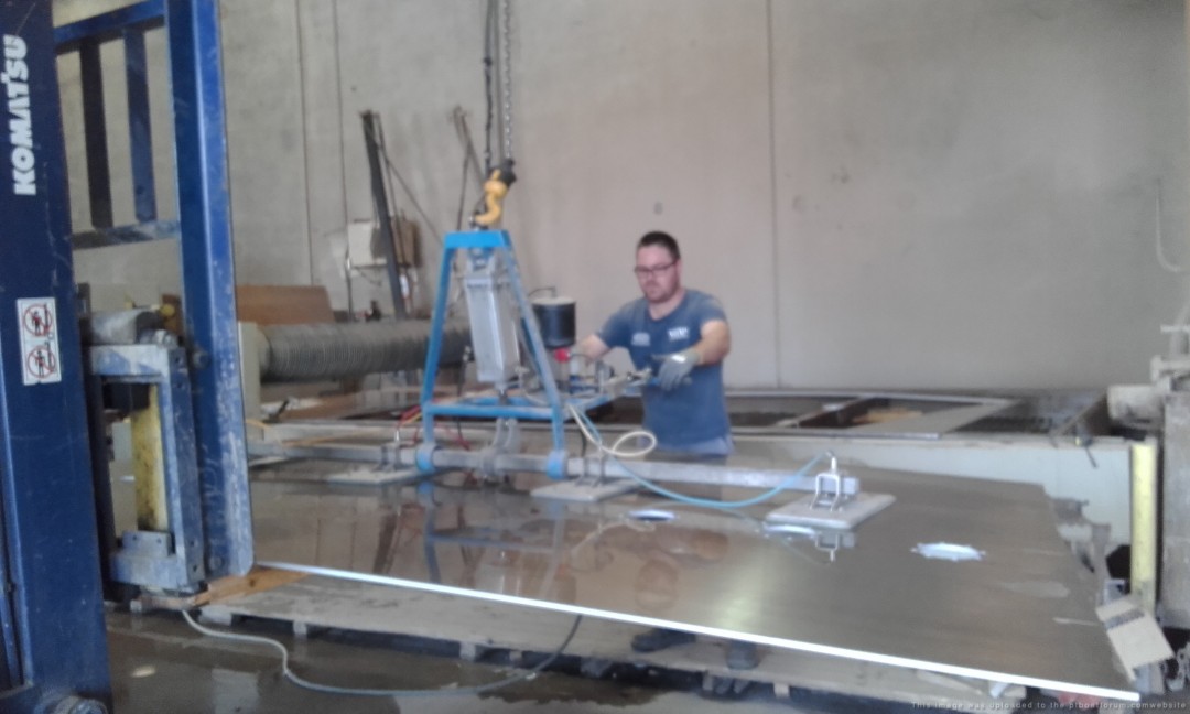
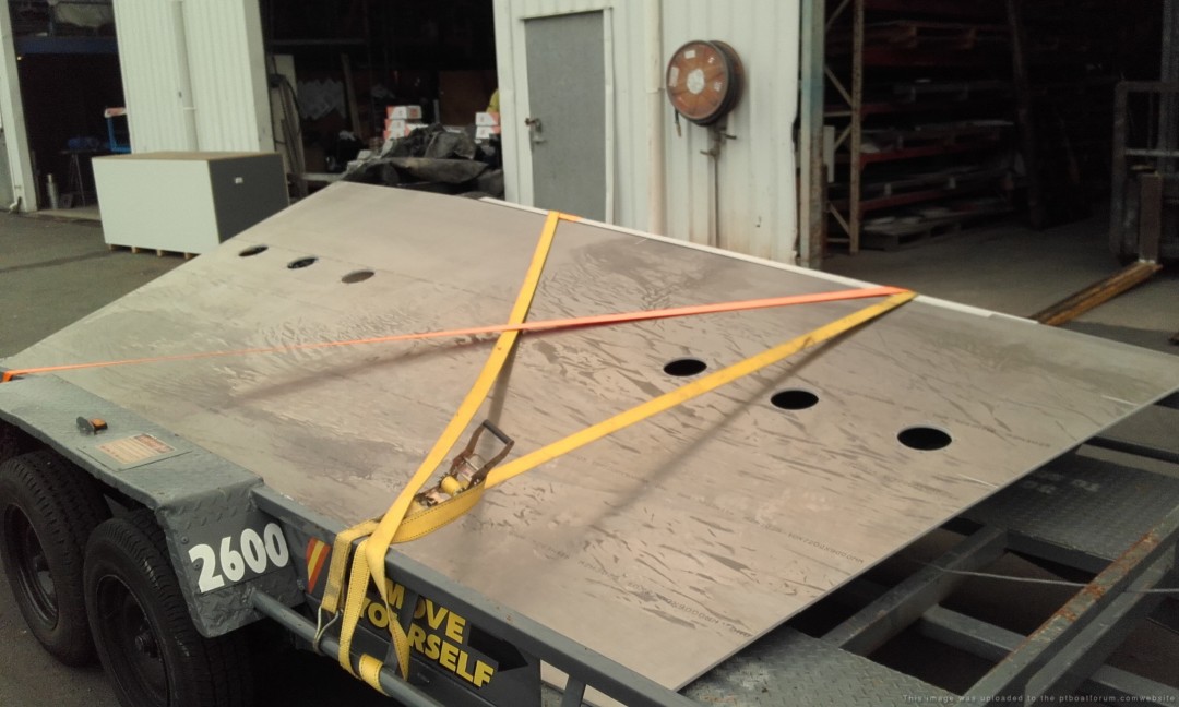
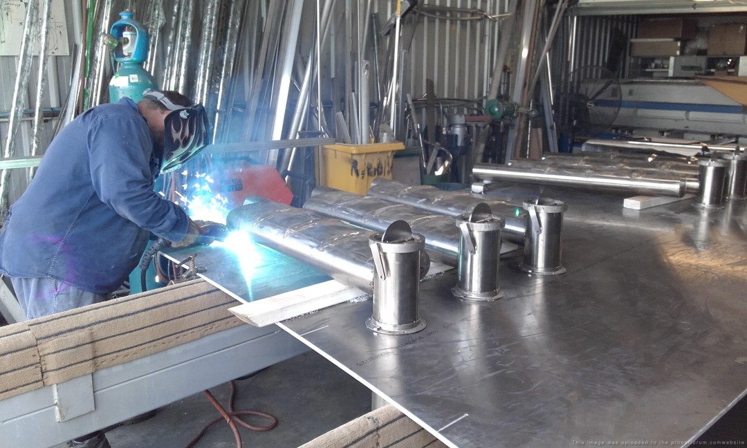
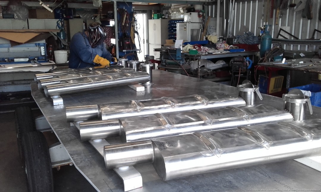
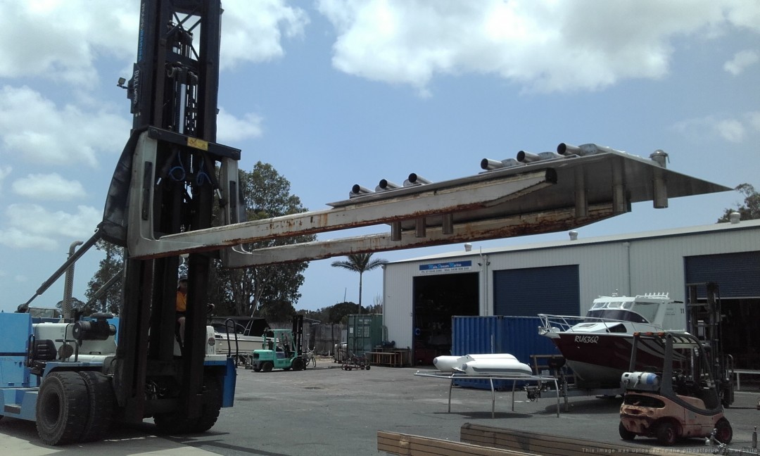
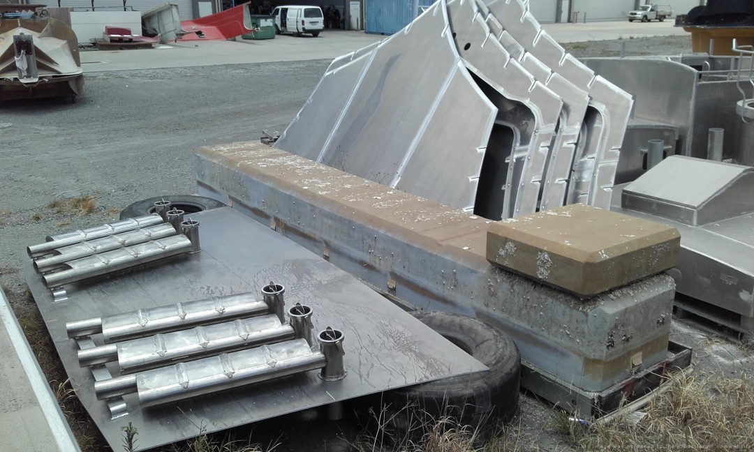
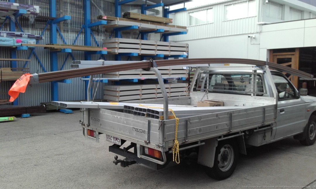
Material for the coamings (aluminum) and foot rails (TREX, artificial wood):
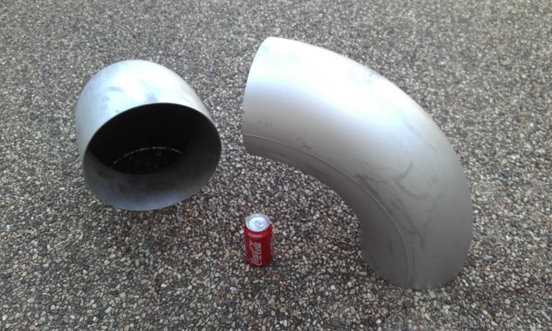
These stainless 10 exhaust elbows are $290 each (ouch), 12 required:
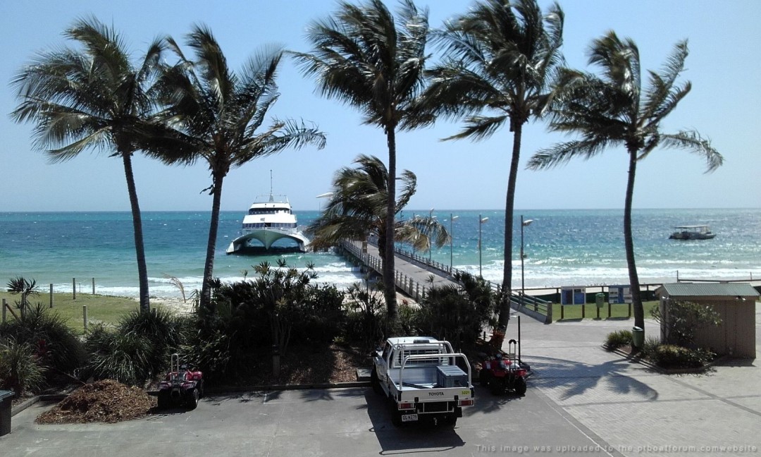
The poor guy has had to take on 2 part time jobs to help pay for his project. The one as a tour guide driving a 16 ton 4x4 bus over the dunes at Tangalooma Resort, Moreton Island requires a commute aboard some old scow:
His other job is as a bus driver for drunken Hens parties, the poor poor man:D


If anybody would like to help with funding, Paul would greatly appreciate it. This is one great big hole in the water for one (semi) retired mechanic to try to fill with money.
Posted By: Jeff D | Posted on: Dec 22, 2019 - 9:25am
Total Posts: 2203 | Joined: Dec 21, 2006 - 1:30am
keep up the good work being a welder I know how hard it is to weld aluminum it can blow a hole faster than you can say PT if your not paying attention!! it takes young eyes to see the difference in the puddle before it blows away. all too shiny. I would come help weld but my eyes are way too old. looks like a tough gig driving that gaggle of hens!!
Scott Campbell 2nd gen,PT 248
Ron 20
Posted By: Scott C | Posted on: Dec 22, 2019 - 12:45pm
Total Posts: 114 | Joined: Nov 20, 2019 - 4:34pm
Hay Jeff, tell your friend, the next time he surrounded by such homely women, I would make the supreme sacrifice and hurl my body on top of them to protect him!
Seriously though, I wish I could send some money, it is an unbelievable quest he is on! Unfortunately, I am eyeball deep into a 1890 Queen Anne house, which is a pile of fancy lumber that will eat up all the money you can throw through the front door.
I try to remember, there will be some people in the distant future who will thank us for this trial of money, blood, sweat and tears!
Posted By: Stearman | Posted on: Dec 22, 2019 - 9:00pm
Total Posts: 151 | Joined: Nov 1, 2017 - 9:38pm
LOL at body hurling, and I recently read an article about restoring historical homes. You (and your bank account) have my sympathy! Do you have to go through such things as using original wood types (even if painted) and traditional woodworking methods? I think that's only for a special class of restorations, from what I remember reading.
My biggest money hole was restoring an old vette, 3 years of blood sweat and tears and tens of thousands of dollars. I had everything working for about a whole week!
Posted By: Jeff D | Posted on: Dec 23, 2019 - 7:01am
Total Posts: 2203 | Joined: Dec 21, 2006 - 1:30am
There not that strict here, but I have tried to use as much original hardware as possible. I can't imagine doing this before the internet, I could have gone to a hundred garage sales and not found one doorknob, let alone entire rare mortise lock sets. When this is all done, I am going to look for a classic car to have some fun. I have restored many classic motorcycles, ranging from pre WWI through the 40s.
Posted By: Stearman | Posted on: Dec 23, 2019 - 8:00pm
Total Posts: 151 | Joined: Nov 1, 2017 - 9:38pm
Has anyone thought of starting a go fund me for this PT boat build?
[url]https://www.gofundme.com[/url]
Posted By: Travis B | Posted on: Dec 24, 2019 - 9:04am
Total Posts: 129 | Joined: Nov 23, 2019 - 10:11am
Thanks Travis I'll bring that up to him.
Posted By: Jeff D | Posted on: Dec 25, 2019 - 4:16am
Total Posts: 2203 | Joined: Dec 21, 2006 - 1:30am
Merry Christmas and Happy New Year to all,
I had the privileged to spend a couple weeks traveling around the Munda, New Georgia/Rendova area with Paul back in 2008. We found some neat things and although my main interest "then" was the PT boat situation in Rendova Harbor and a USAAF B-17 wreck on the island- it soon blossomed into so much more mainly being the US MIA in the Solomons.
Paul's enthusiasm into all things PT helped keep my interest alive during return trip's down island (2009/2012), but the MIA subject was my primary focus. Paul is doing a great work in keeping the memory alive over there in OZ and if you make it over there look him up and shout him a beer..lol..great conversation!
My interest in the PT boats has never left, but the MIA will always be my number one priority now- and that work is endless and often well beyond my budget; however, like Paul I will carry on.
For those of you doing the books and such- Munda and surrounds will grow and the history will get covered, or scrapped - so the time is now to get out to those old sites..someday they will be gone forever. There is soooo much to follow up on stories, rumor's, wrecks..
One rumor I remember and did not pursue is someone on one of the island villages in Rovianna lagoon supposedly has the wheel (helm) of a PT boat- I do not recall how this came up in conversation, but the local telling me this was fairly certain it was from a PT boat. I do not know if it was from the two that went on the reef nearby, or the one that was is (in WW-II) partly in the shallows off Lumbari island..or even from a PT boat?
Millions of stories-
Posted By: Shaneo2 | Posted on: Dec 26, 2019 - 7:54pm
Total Posts: 147 | Joined: Apr 17, 2008 - 10:19pm
Shaneo2:
Happy New Year!
That wheel could be from one of 4 boats, 117, 153, 158 or 164. (a 5th boat and real long shot would be PT 166, but I believe this was sunk in deep water, in the area) it would b great to find it/buy it from the local, if it is a true ELCO wheel.
Take care,
TED
Posted By: TED WALTHER | Posted on: Jan 3, 2020 - 10:14am
Total Posts: 3091 | Joined: Oct 16, 2006 - 7:42am
Paul sent me an update, full speed ahead and damn the torpedoes! Most excellent Paul, you sure know how to get things done even in tough times:
[green]Hi Jeff.
Latest update as at May 21, 2020.
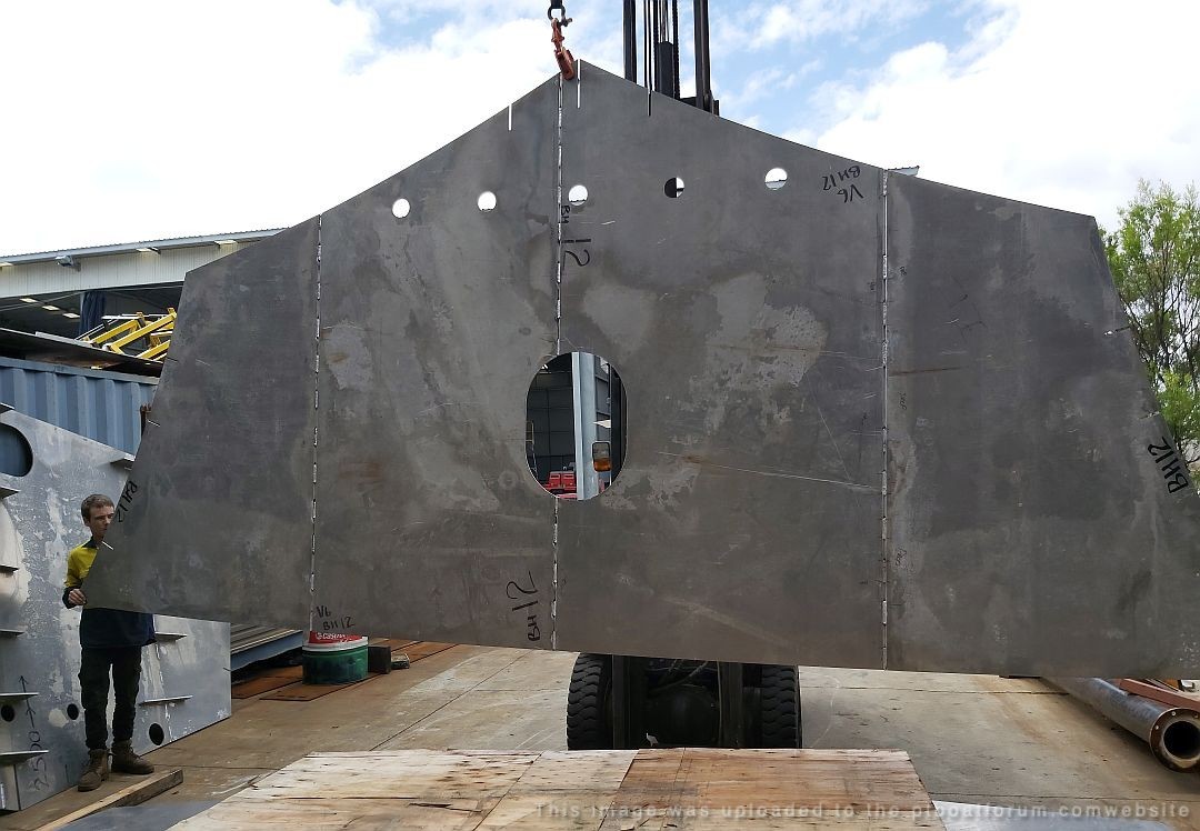
All 5 bulkheads and all 35 frames now completed.
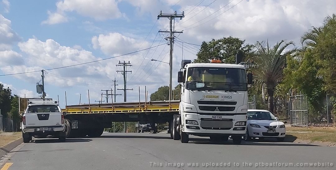
Big trucks required to transport these components. ($$$$)
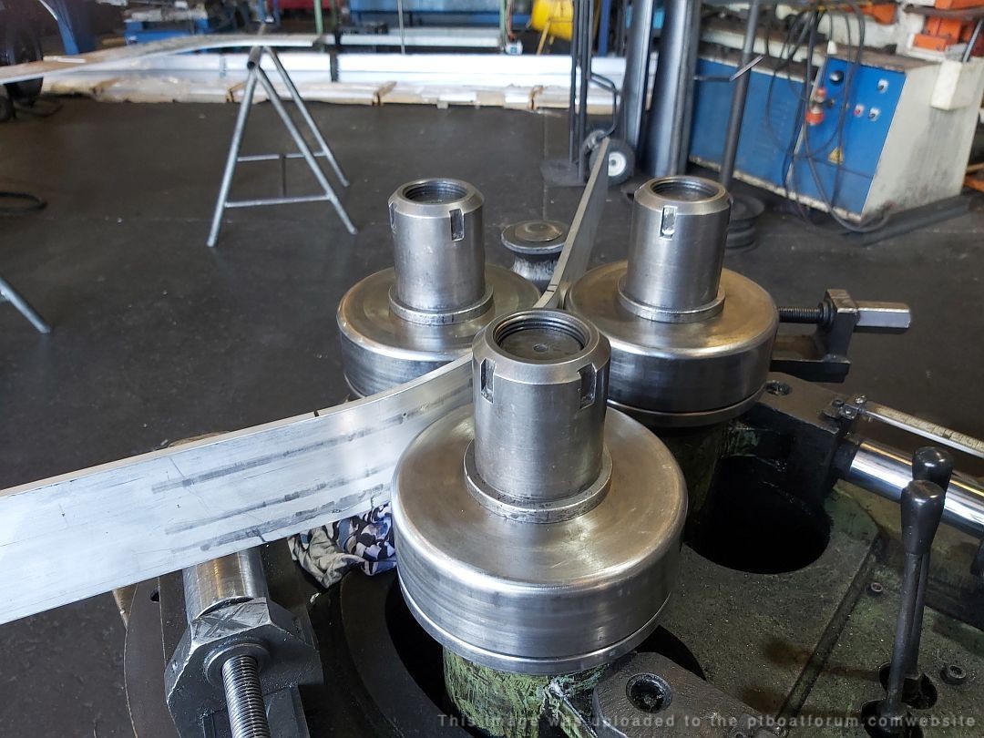
Frame rider fabrication specialized equipment,
expensive, but makes the assembly fit perfect.
For the technically minded.........
10mm 5083 H116 DNV aluminum
Welding to x ray quality and destruction test sampling.
Weld machine Fronius 320 pulse* mig with 1.2mm 5356 wire.
The Fronius welder is the latest intelligent version.
The cutting edge boat builders in OZ have ditched their Millers and Lincolns.
After imputing the parameters - material grade, thickness, filler wire grade and size,
deposition mode required.......consistent perfect welds. (and, 100% duty cycle ! )
After just 1 week of training on these welders........perfect welds.
Watching these machines in action is like having a cup of tea with God.
* pulse mig is the difference between a weld and a perfect weld.
Zero income having an effect on construction timeline, as expected.
But, as usual..........Damn the torpedoes......full speed ahead.
Starting now on the hull longitudinals and engine girders.
(engine girders are 5m x 1m x 16mm thickness........4 required)(5083 ally of course)
Also, deck scantlings.
( 50mm x 75mm x 6mm angles......16 x 80 feet = 1280 feet .....there are 1320 feet in a drag strip!)
Pedaling as hard as I can.
Stay safe Jeff.......and many thanks for your assist to date.
Paul.
(model boat builder, scale 1:1)
(Elco - Australian division)[/green]
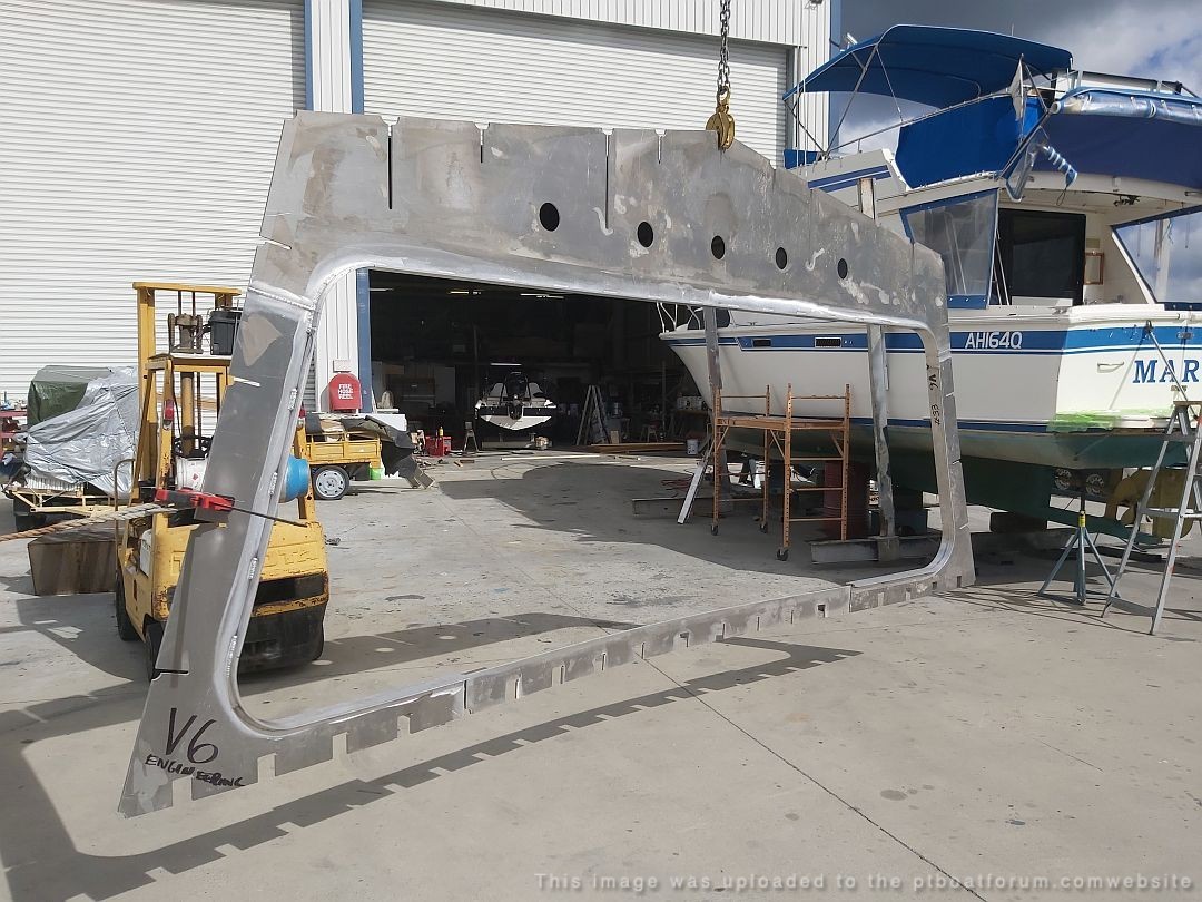
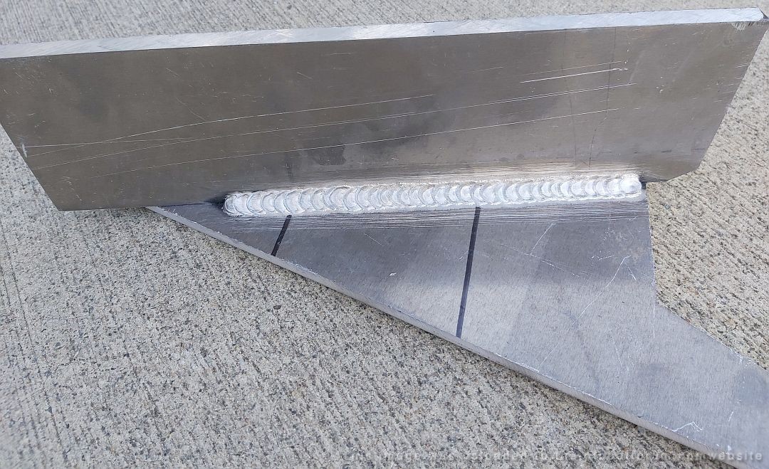
Posted By: Jeff D | Posted on: May 24, 2020 - 9:55am
Total Posts: 2203 | Joined: Dec 21, 2006 - 1:30am
MIND-BLOWING PROJECT...
Will
Posted By: Will Day | Posted on: May 24, 2020 - 2:04pm
Total Posts: | Joined: Unregistered
Paul, what a great job you are doing. as stated before as a welder I know the old school way of welding aluminum with TIG and feeding wire. new technology and computers are great. Maybe these old eyes could do the welding after all ! just need a few thousand and the wife's permission- that would be the hard part!! for the trip down under during your summer. Again great job!! Scott[:-smilearound-:]
Scott Campbell 2nd gen,PT 248
Ron 20
Posted By: Scott C | Posted on: May 24, 2020 - 2:18pm
Total Posts: 114 | Joined: Nov 20, 2019 - 4:34pm
Yah Will for sure.
Paul mentioned that he'll be following Elco's upside down hull construction method:
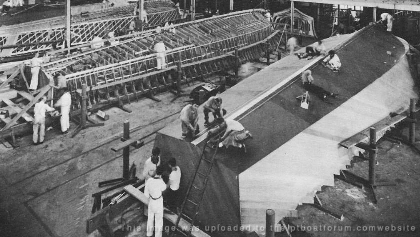
Posted By: Jeff D | Posted on: May 25, 2020 - 6:46am
Total Posts: 2203 | Joined: Dec 21, 2006 - 1:30am
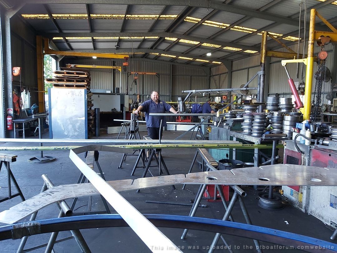
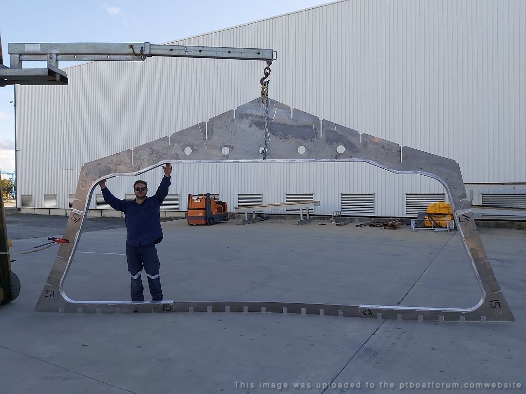
Paul sent an image that shows the scale of his massive project well:
[green]Last of the frame pics to show the 1:1 scale size of this model boat components.
That's Dan my welder guy.
Certified ISO, DNV, Lloyds, USL and Australian Standards Association.
FYI, Australian company, Austal, builds 15% of the US Navy fleet.
(high speed aluminium vessels)
I am starting on the hull longtitudinals now.
(engine bearers / hull stiffeners / scantlings)[green]
Posted By: Jeff D | Posted on: Jul 2, 2020 - 10:16am
Total Posts: 2203 | Joined: Dec 21, 2006 - 1:30am
Any guess-ta-mates as to the total cost of this epic undertaking?
Will
Posted By: Will Day | Posted on: Jul 3, 2020 - 3:42pm
Total Posts: | Joined: Unregistered
My guess would be "boat loads". :D
I sent him an e-mail asking.
Posted By: Jeff D | Posted on: Jul 4, 2020 - 11:22am
Total Posts: 2203 | Joined: Dec 21, 2006 - 1:30am
Hey Will, I received some excellent advice from Paul regarding your question:
[green]Consider the basics.
Why do you want to build it ?
How much money have you got ?
How much money can you get ?
There are 2 main start points.
A ) Do you build to commercial standards ?
(USL / US Coast Guard / DNV / Lloyds)
(in Australia it is called Commercial survey)
This build allows charter -for fee or reward.
or,
B ) Build for private / recreational use only.
A) allow 2-3 million dollars
B) allow 1-2 million dollars
How do I know this ?
I don't even have to answer that......it's obvious.
You can reduce these costs a little.
(underline.....a little),
by doing most of the work yourself.
Especially in a private build, like mine.
When you build commercial, you are locked into a VERY expensive process.
VERY expensive.
Government regulations fill books.
My advice to start.
Buy a 1/35 Italeri PT109 model.
Don't glue it together.
Just stare at all the parts for ONE month.
Consider how much every part would cost to reproduce scale 1:1.
Then consider how much these parts in a WORKING vessel would cost.
Next step.
Obtain estimates (not quotes) from boat builders.
(be sitting down)
Still interested ?
Then, engage a qualified Naval Architect to draw up the plans.
You CANNOT do this yourself, no matter what field of engineering you specialize in, no matter how clever you are at CAD / CAM design.
How do I know this ?
You cannot build a rocketship unless you are a rocket scientist.
Do your research.
For example........allow AT LEAST $50,000 for a competent Naval Architect to draw up complete plans.
That's what I had to pay.
This is an 80 foot, high speed patrol boat.
This ain't no Bass boat !
FYI,
My 2 x USED engines + gearboxes......$100,000 +
Replica helm.............$1,200 (could have purchased standard helm for $90)
Check out the costs of your proposed engines / gearboxes.
Wooden build completely out of the question.
That's easy $2.5 million.
IF you could find the craftsman.
With an aluminium ( USA - aluminum ) build,
decide on Routing, Laser or Waterjet cutting components.
The list goes on, and on, and on, and on, and on, and on.....you get the picture.[/green]
LOL eh? [:-laughing-:]
Posted By: Jeff D | Posted on: Jul 8, 2020 - 2:43pm
Total Posts: 2203 | Joined: Dec 21, 2006 - 1:30am
LOL - Mind-boggling...
Will
Posted By: Will Day | Posted on: Jul 9, 2020 - 10:07am
Total Posts: | Joined: Unregistered
Sounds like a real labor of love! The most noble of quest!
Posted By: Stearman | Posted on: Jul 9, 2020 - 9:12pm
Total Posts: 151 | Joined: Nov 1, 2017 - 9:38pm
Paul has been busy working on the 20mm, he plans on adding a propane powered firing system for those too slow in giving right of way. He is also relieved that parts of Australia are being opened up and he's able to get back to work. PT boat construction ain't cheap!:
[green]Tangalooma Wild Dolphin Resort has opened up again, and I am working there now.
Financial relief at last !
Party bus rocking with heaps of drunk hens. (pic attached for your viewing pleasure)
Life is good again.[/green]
Paul has a great deal of respect for JFK, the man that inspired his project. He had this to say:
[green]I have ordered crew dixie hats and one CO hat.
It is my intention to never wear the Captains hat or uniform.
I am not JFK's bootlace.
Never will be.
I will allocate the CO hat to others on board.
That is my plan.
(better build the boat first !)[/green]
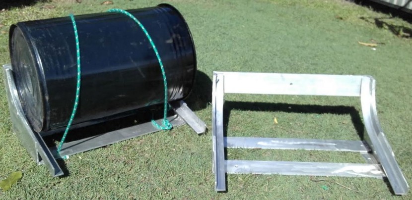
Some photos of the 20mm cradle construction. He used a Toyota Landcruiser wheel hub as the base of the cradle:
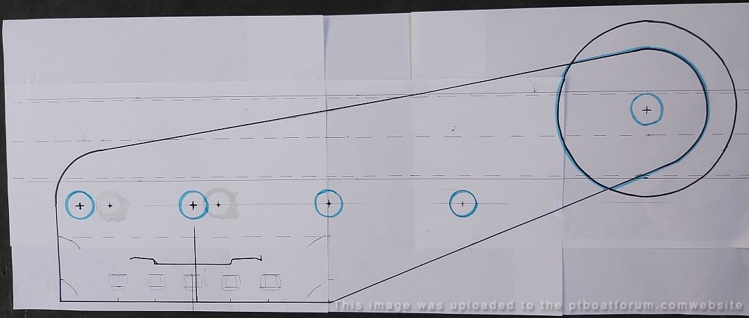
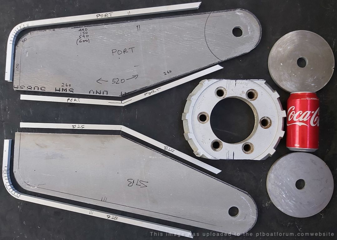
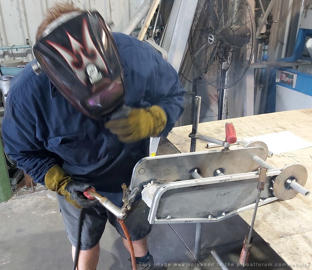
Poor guy, having to slave away in this kind of work environment:

Posted By: Jeff D | Posted on: Aug 13, 2020 - 6:31am
Total Posts: 2203 | Joined: Dec 21, 2006 - 1:30am
That last photograph reminds me, tell Paul, he's a braver man then I! Love the progress photos, please keep them coming.
Posted By: Stearman | Posted on: Aug 13, 2020 - 9:41pm
Total Posts: 151 | Joined: Nov 1, 2017 - 9:38pm
Hah! I'll bet he's seen some stuff, especially later in the evening when the booze is flowing freely. And him being a kid in a candy store with no money.
Posted By: Jeff D | Posted on: Aug 14, 2020 - 3:16am
Total Posts: 2203 | Joined: Dec 21, 2006 - 1:30am
Boat not even finished, and already a full crew aboard...
Will
Posted By: Will Day | Posted on: Aug 14, 2020 - 9:23am
Total Posts: | Joined: Unregistered
Very nice crew you have.[:-cheers-:]
Bill P Reese
Posted By: billpr | Posted on: Aug 14, 2020 - 7:40pm
Total Posts: | Joined: Unregistered
Any updates on this? Thank you to whomever pointed me to this thread! What a huge project! I’d love to see more photos.
Posted By: dreimer | Posted on: Apr 3, 2021 - 7:11pm
Total Posts: | Joined: Unregistered
Paul is pretty amazing, he is doing all this while working to help pay for it all. He lets nothing stop him, he just jumps right in and lets his ingenuity take charge. Hopefully he will have an update and more images to share with us soon.
Posted By: Jeff D | Posted on: Apr 4, 2021 - 9:05am
Total Posts: 2203 | Joined: Dec 21, 2006 - 1:30am
Thanks Jeff for the reply. I looked through all the posts in this thread, but didn't see if Paul is going to go ALL Aluminum, or is he going to do the hard-chined plywood? It's going to be pretty heavy, with all aluminum?
Posted By: dreimer | Posted on: Apr 5, 2021 - 6:42pm
Total Posts: | Joined: Unregistered
You're very welcome. It will be all aluminum, I don't know how the weights would compare though. I think you may be right, the Navy made 2 PT 8's, 1 wood and 1 aluminum and if I remember correctly the wood one was lighter.
Posted By: Jeff D | Posted on: Apr 6, 2021 - 5:25am
Total Posts: 2203 | Joined: Dec 21, 2006 - 1:30am
It makes sense to go all aluminum. The wood would require a LOT more money/time, and be harder to maintain over the years. I'd still like to see a half scale. Even with the 77' model, it'd still be a pretty sizable boat!
Posted By: dreimer | Posted on: Apr 7, 2021 - 4:48pm
Total Posts: | Joined: Unregistered
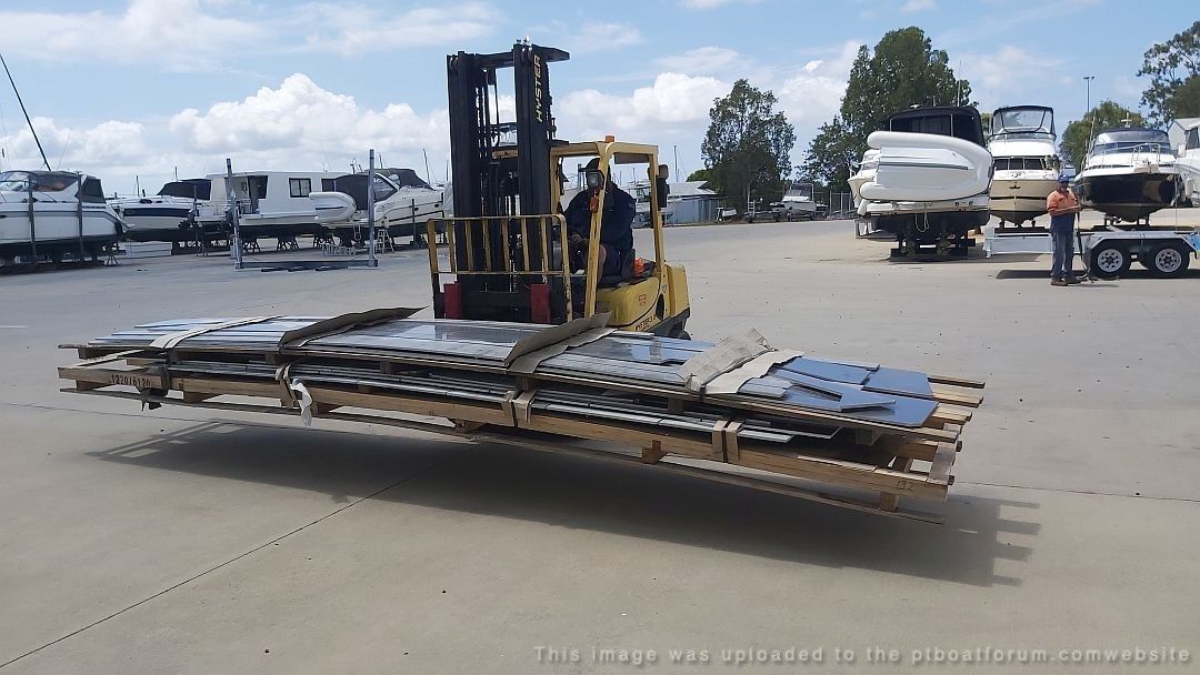
Paul sent some images of his project along with a few work pics showing him hard at work earning money to help pay for his amazing project. It's a dirty job but someone's got to do it! :D
A few words from Paul:
[green]FOLLOW THAT DREAM.
Hi Jeff.
Against all odds, Project PT109 (model boat, scale 1:1) has officially reached the 2/3 milestone.
ALL hull components now completed.
Next step is gluing the model together.
In the words of a classic rock song, Life has it's problems, I have my share ,
so when the going gets tougher than usual, I just crank up that Elvis song....FOLLOW THAT DREAM.
Helps.
Next steps include selecting a 100ft x 40ft build shed, near the water.
Purchase a Hino / Isuzu flat bed truck with 6 meter crane boom for hull build.
Calculating and paying for a VERY substantial amount of 5356 filler wire and truck loads of Argon welding gas.
Photos for your amusement.........
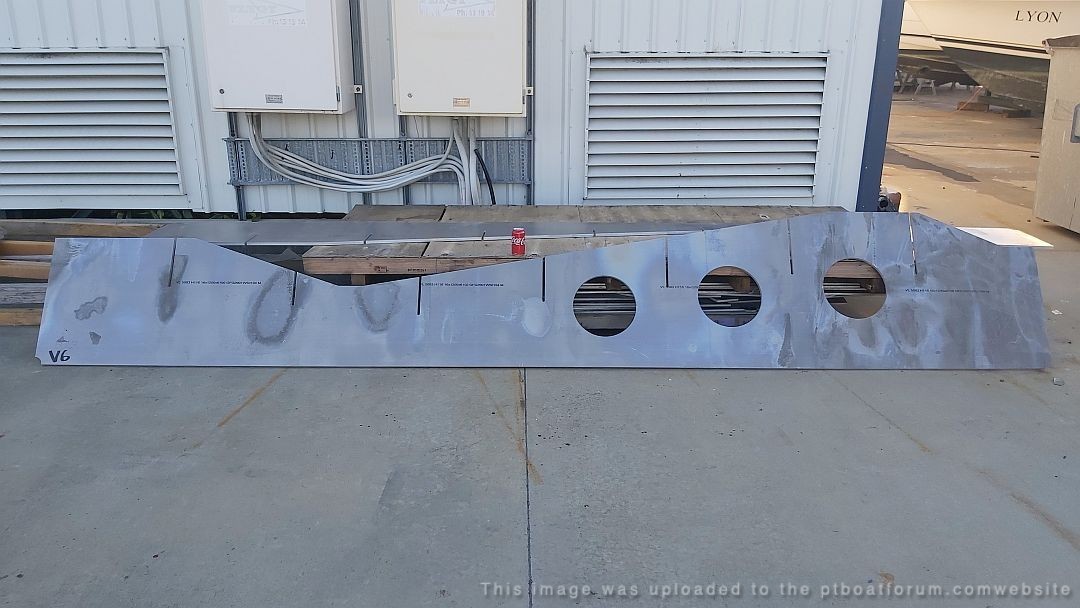
Engine girders.
1 of 4 @ 5 meters long, 16mm thick 5083 alloy.
With 2 x 3 ton Caterpillar V12's and twin Disc gearboxes,, these need to be substantial to deal with the slamming forces involved at 45 knots.
The 300mm holes for sump access (ex mechanic here! ) will be re inforced with 100x10 flat bar riders.
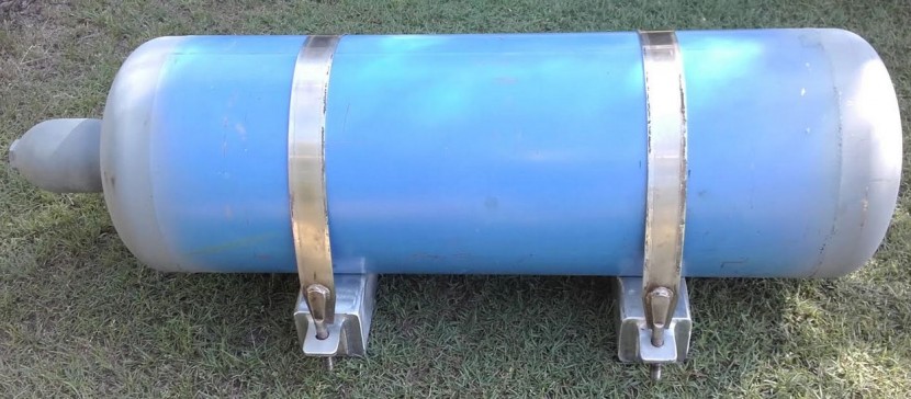
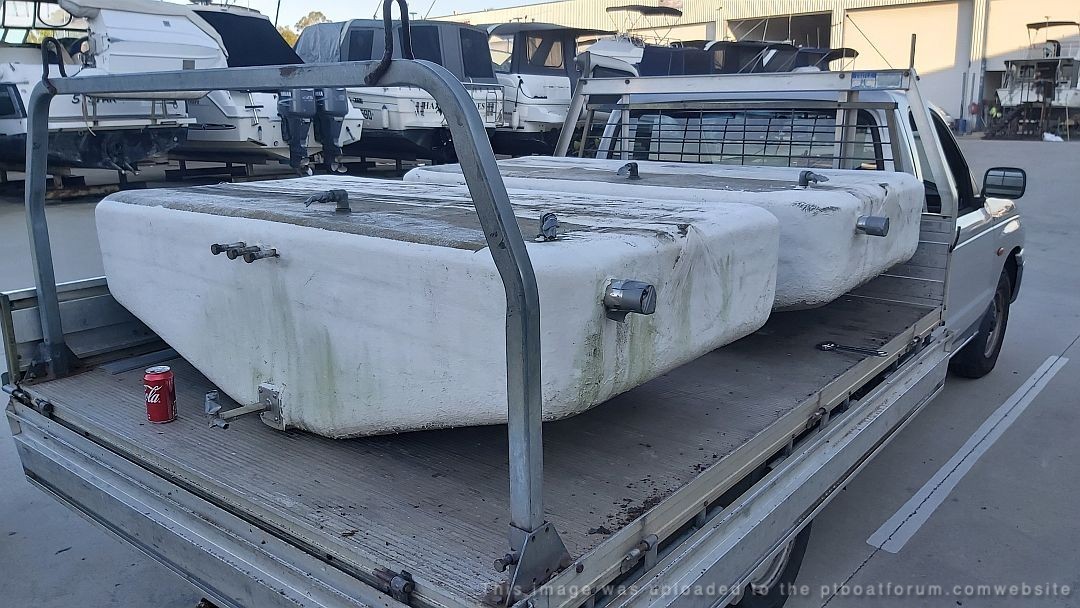
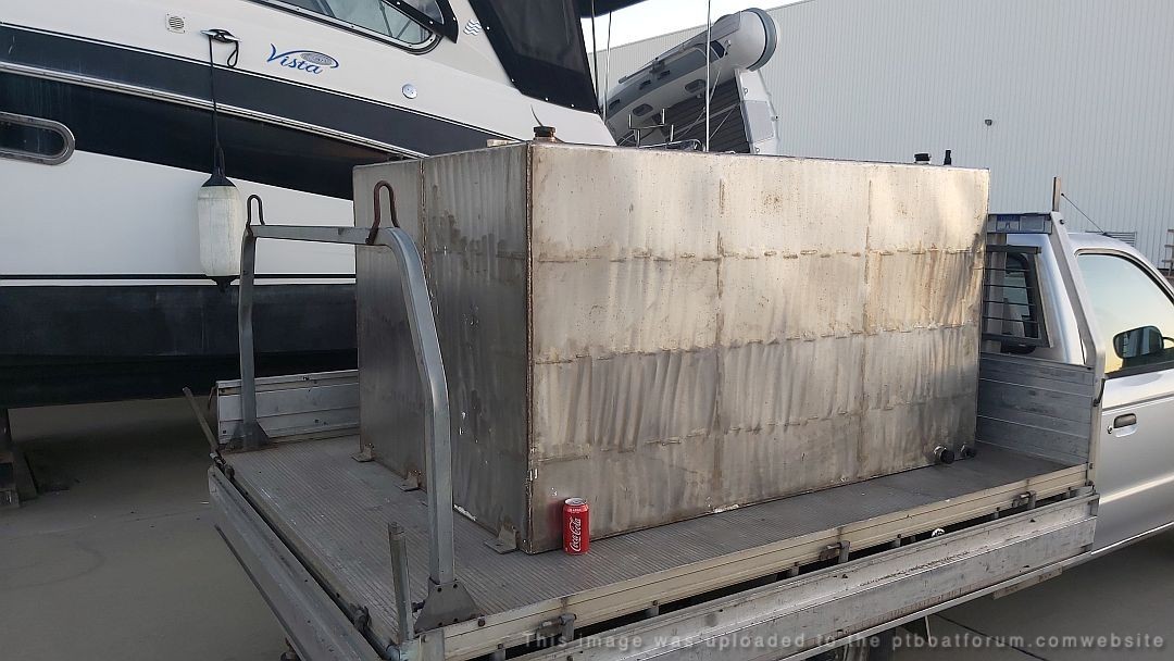
3 x 600 liter FWD fiberglass fuel tanks.
2 x 1000 liter AFT 316 stainless tanks
(fill cost @ $1.40 / liter......?.......a LOT ! )
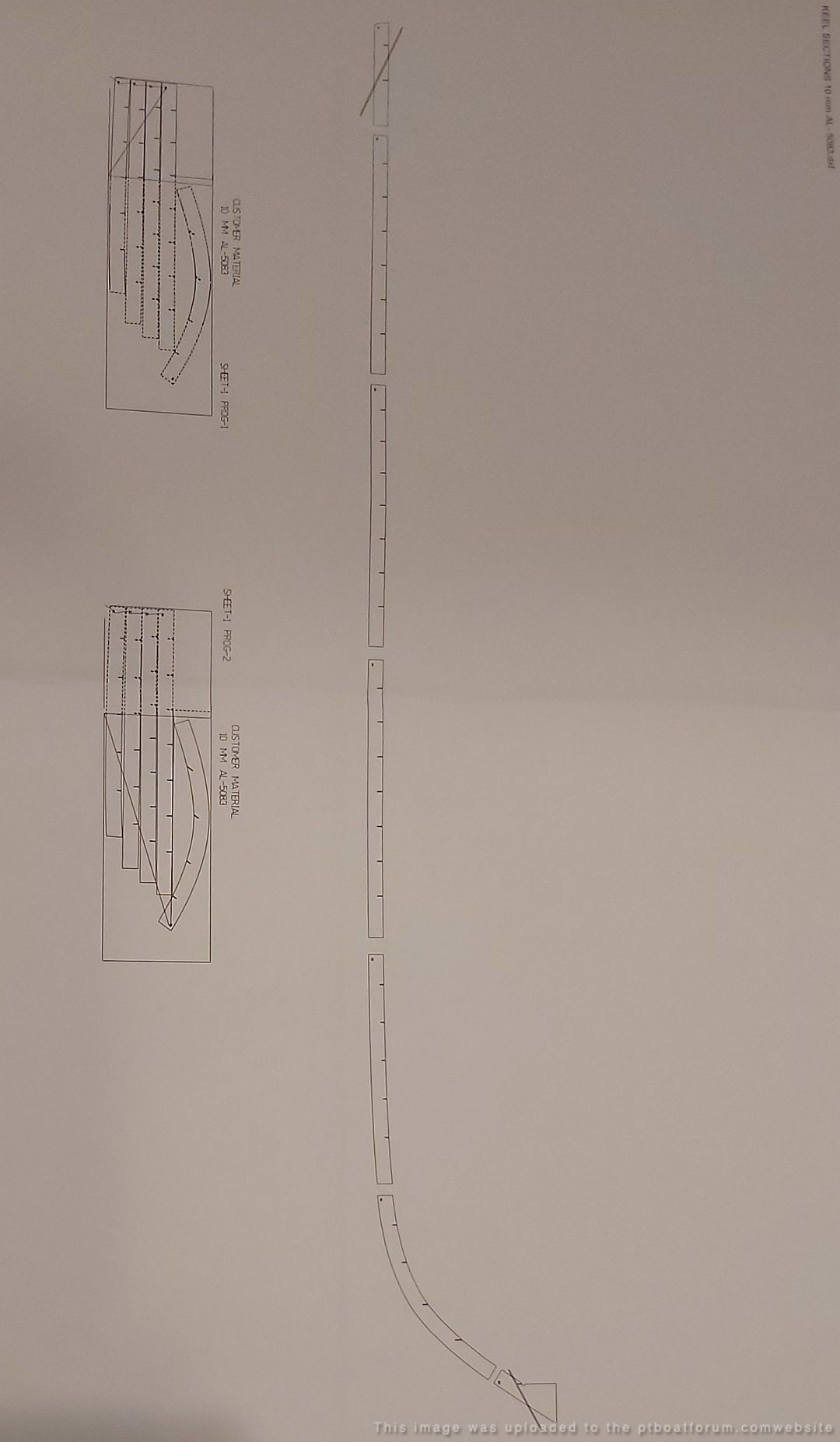
Keel PDX computer cut file....80 foot, plus stem.
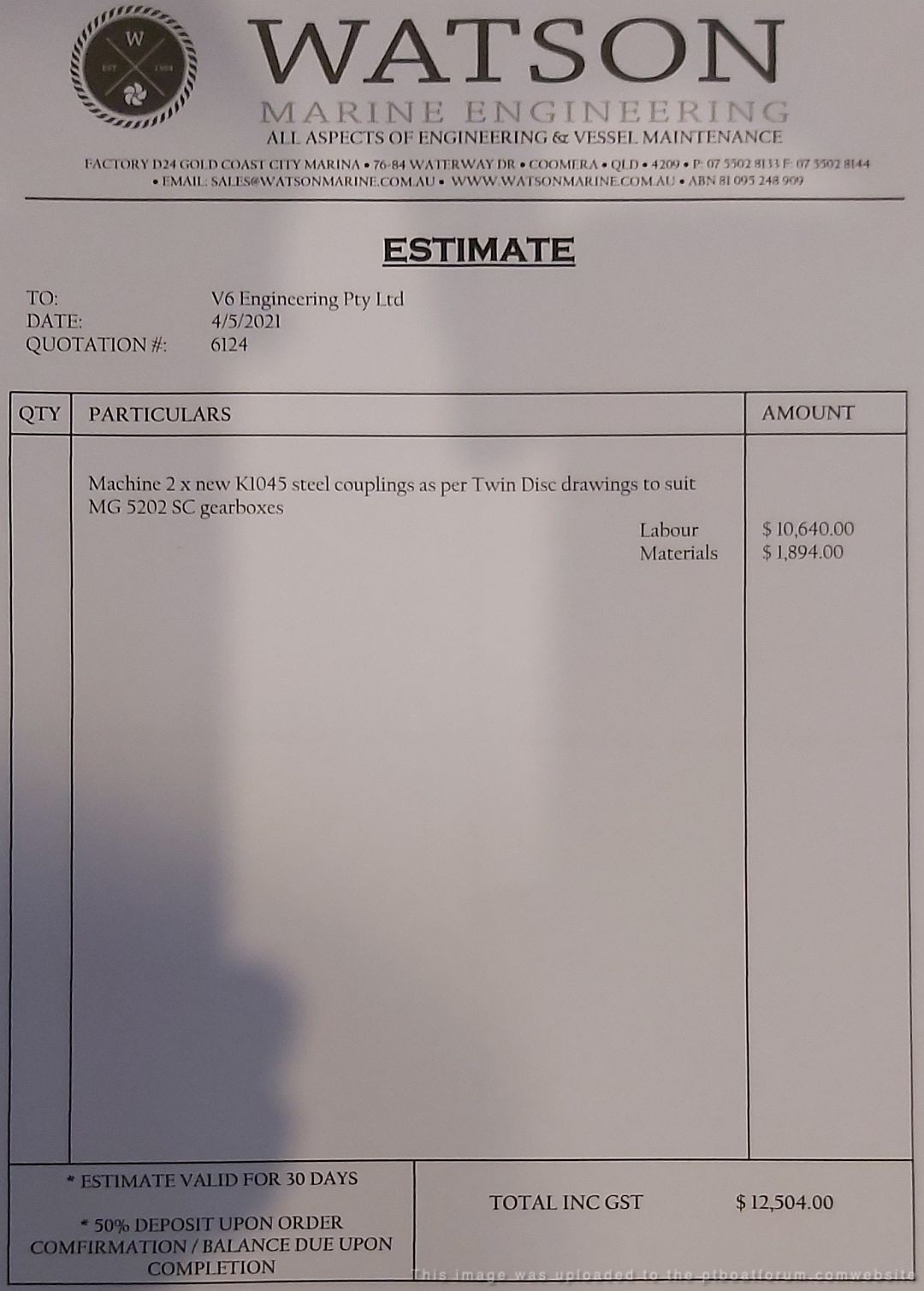
Quotation for 2 x gearbox couplings.
Forklift hire and storage costs mount up.
Crew applicants will require Navy regulation uniforms.
FOLLOW THAT DREAM.............
Cheers,
Paul.
(model boat builder, scale 1:1)[/green]


Posted By: Jeff D | Posted on: May 19, 2021 - 6:11pm
Total Posts: 2203 | Joined: Dec 21, 2006 - 1:30am
Well Jeff, Paul is living proof, that in order to enjoy your toys, a man must first suffer through his day job!
Posted By: Stearman | Posted on: May 19, 2021 - 7:57pm
Total Posts: 151 | Joined: Nov 1, 2017 - 9:38pm
Truly mind-boggling. All of the talk and what-ifs, and here's someone who is actually living his dream.....DRIVE ON!
Will
Posted By: Will Day | Posted on: May 21, 2021 - 12:16pm
Total Posts: | Joined: Unregistered
I received an update from Paul today. It sounds like he is going full steam ahead! He also has some questions for us, and some well-deserved praise for Dick's awesome art:
[green]Progress on the model boat is unceasing.
Not a day goes past without some additions.
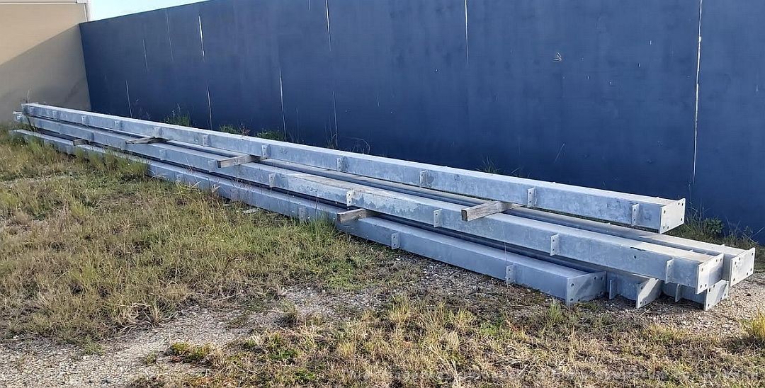
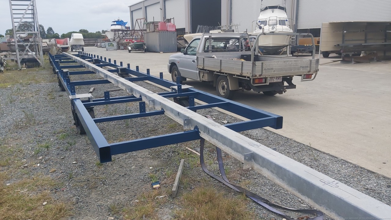
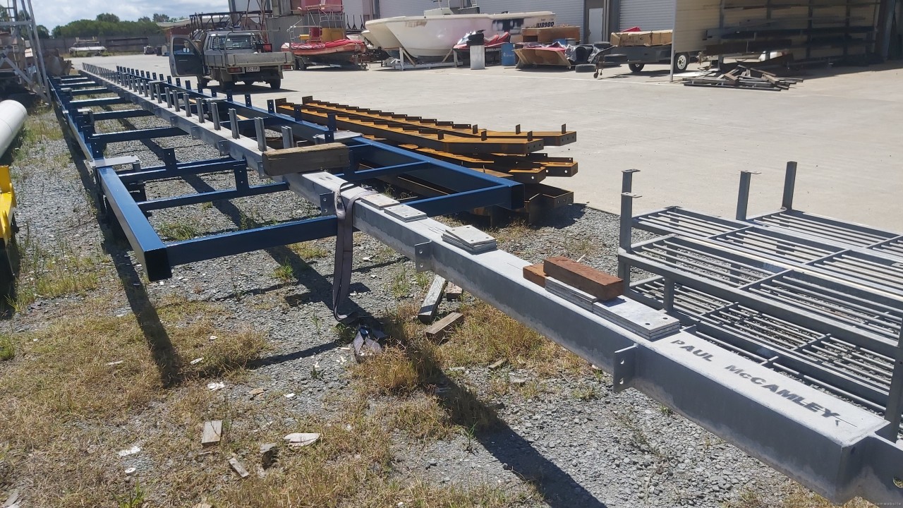
This week a lucky purchase of 6 x 11 meter lengths of galvanized steel square tubing.
This will be part of the hull build frame, dynabolted to the concrete floor..
Bonus is the welded tags with mounting holes for frame alignment brackets.
I got lucky !
More steel will be required for hull build alignment frame, using lasers to precisely position frames.
Got to keep on moving !.
I have some questions for the Forum members with regards to the mindset of PT Boat designers.
1) International Laws of the Sea require vessels to Give way to starboard.
That is why most vessels, but not all, have the helm on the right hand (starboard) side of the vessel.
This gives a clear view to avoid collisions.
Why did the PT boat designers place the helm on the port side?
2) Why did the Elco 103 series PT boats have a curved (S) sheer (gunwale line).
(Italeri famously got it wrong on the 1/35 scale model)
(as well as cabin sides not plumb to baseline)
(In the 1:1 model build, this factor alone caused a considerable amount of calculations and head scratching)
I can see no practical on water advantage in increasing the build complexity with such a sheer.
Such a sheer would appear to be purely aesthetic only.
3) Hull shape in plan view has the beam markedly wider than the transom.
Modern high speed planing vessels are mostly almost parallel.
I know it works with the old school shape, because hundreds were built and worked.
But how much better / more efficient would a parallel hull shape perform?
Is it a manoeuvre ability advantage - high speed turns ?
Perhaps a Naval Architect could comment.
4) Differences between Elco and Higgins machine gun turret placement are puzzling.
Obviously the Elco MGs could be both brought to bear on one side, maximizing the firepower.
Higgins......only one side for a broadside pass.
Big difference, but for some reason, Higgins designed it that way, and the Navy signed it off.
5) Elco 'V'drives versus Higgins straight shaft drives.
Anybody care to calculate the power loss on those 'V'drives, and possible top speed loss?
6) Without doubt, the worst job on a PT boat..........
Motormacs sitting on a very small seat on top of incredibly hot, noisy, fumey engines.
Just to shift gears.
Surely with the throttle levers controlled mechanically at the helm, gear selection could also have been easily incorporated at the helm position.
(aircraft of the day had multiple complex cable systems, basic engineering)
The Skipper would have complete control at all times.
Relying on helm to engine room message relay, would be problematic, to say the least.
Especially in a battle situation.
(maybe why JFK (Crash Kennedy) hit the dock shed !)
Was this just a carry over mindset from the BIG ships ?
I would like to finish with a standing ovation for Dick's absolutely awesome PT Cutaway drawings.
Incredible, how much work went into these amazing works of art.
Without doubt the most outstanding contribution to the PT heritage I have ever seen.
Take a well earned bow Dick.
You are the man.
Stay safe my fellow USA PT enthusiasts.
Warmest regards.
Paul.
(model boat builder, scale 1:1)[/green]
Posted By: Jeff D | Posted on: Jun 20, 2021 - 9:55am
Total Posts: 2203 | Joined: Dec 21, 2006 - 1:30am
Hello Paul, I dont really have the answers to most of your questions except for two of them. The first one, question #4 about the Higgins 78 foot 50 cal turrets vs the Elco 80 ft turrets being offset and how it relates to broadside firepower. So the design of the 78 foot Higgins was not too far from the 77 foot Elco design. As you may recall, the 77 foot Elco had its 50 cal turrets next to each other just like the Higgins design. The Elco 80 footer was a complete redesign, and perhaps the Higgins Company was asked, but declined to redesign their entry to match the Elco changes. I get the feeling that is not how Government contracts worked. Higgins just chose to stick to the original setup that was accepted by the Navy for the Plywood Derby. I imagine there was some friendly competitive spirit between these 2 companies, and they would not take kindly to being ordered to adapt their competitors designs into their own boat. It would be like the Government telling Ford to start installing the Onstar Navigation System (patented by General Motors) into their Ford autos. It is an unacceptable change, and was not in the contract, so it was not installed.
The other question (#6) I can answer is about the WW2 PT Boats not having a remote gear shifting capability. I think I know exactly why. It is based upon the design of the Packard engine transmission. The Packard engine uses a Snow Nabstedt "Joes Gear" Transmission which is 3 position transmission. (forward, neutral and reverse). The shift lever takes about 70 foot-pounds of torque to place it into or out of gear. When the PT658, here in Portland, OR was first being operated in 2004, we installed some pneumatic cylinders in order to operate these shifters from the helm. That was a bad choice, since it created other problems. What happened was the constant shifting by the Skipper when coming into a dock was wearing down the transmissions extremely fast. We were having to replace the drive band on the reverse gear and other internal parts of the transmission way too often. Also, the guy up on the helm has no feedback from the engine when he is shifting. If the engine started to make noise or groan or bog down the helmsman cannot hear a thing. We developed the opinion that having the ability to shift remotely promoted "overshifting". The skipper has a learning curve of how to come into a dock properly without the necessity of constantly shifting into reverse or forward in quick succession. So we had to break the skipper of this bad habit, and train our motormacs to instantly respond to orders from the helm. Our learning curves resulted in several unplanned high speed meetings between the boat and dock! One of our former skippers Chuck Kellogg told me once that you only want to approach the dock in the PT Boat as fast as you want to collide with it! So we removed those remote shifter cylinders only about 1 year after installing them to help keep our engines running better. Another bad thing about the pneumatic cylinders was they required constant adjustment, and would not place the engine completely into gear, or it would sometimes pop out of gear under a strain. So our crew decided we should just stick to the original WW2 method of having the motormac down in the engine room do the shifting and the skipper would just operate the signals for what he wanted to do. We also added a flashy light and a loud buzzer to get the attention of the motormac in the engine room before ordering a shift, so they would be ready to shift gears as soon as the order is given. It is so loud down there they found the motormacs were missing orders sometimes.
Jerry
Jerry Gilmartin
PT658 Crewman
Portland OR
Posted By: Jerry Gilmartin | Posted on: Jun 20, 2021 - 3:15pm
Total Posts: 1498 | Joined: Oct 8, 2006 - 11:16pm
Hi Paul . . .
I’ll try to answer some of your questions below.
Please note, my design and/or historical comments are my own, and are assumed by me, to be reasonable assumptions from what I have read/observed over time.
[b]Hull Design of Elco boats only - [/b]
(Higgins and Huckins designs were different):
The designs of the late 30’s and 40’s were based on science, engineering, and experience at that time. It’s funny to look back, design engineering was calculate on “Slip-Sticks”, the trusty old slide rules we all learned on, not computers and calculators. Engineering was pencil on paper, not ultra sophisticated 3D and CAD computers, software with analytical abilities, and 3D printers. Just think how simple it would be to make multiple hull mock-up with all types of varying design aspects and test float them . . . something that couldn’t be imagined back then.
[b][red]CORRECTION: I misidentified the boat that was actually purchased by Elco. It was actually a copy of the PV70, ordered by Elco and identified as the MTB-ELCO. The actual PV70 was send to Canada, where it spent the war year being renumbered and reclassified several time. For some reason it was returned to the US Navy at the war’s end.[/red][/b] - (Special thanks to Al and Andy for their help )
[b][red]The sentence below should have read:[/b][/red] [blue]The first Elco boats, PT 10-19 and PTC 1-12, were 70-foot boats based closely on the design of a purchased copy of the PV70 boat from BPB of Great Britain . . . . . [/blue]
The first Elco boats, PT 10-19 and PTC 1-12, were 70-foot boats based closely on the design of the purchased PV70 boat, from Great Britain.
This PV70 boat was a new design from Hubert Scott-Paine’s British Power Boat Company. With the design featuring a low boat profile, a planning hull, hard chine, and a curved gunwale , see photos below.
Photo PV70 (PT 9)
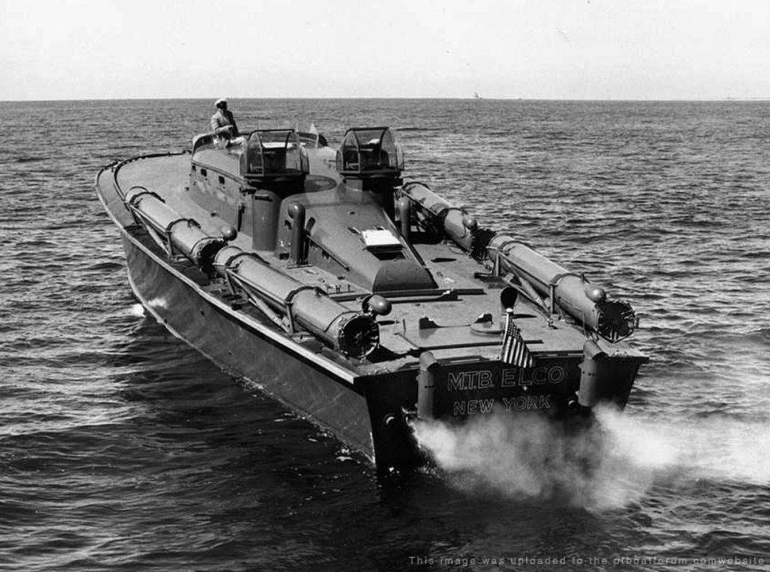
Photo of PT 9 (PV70)
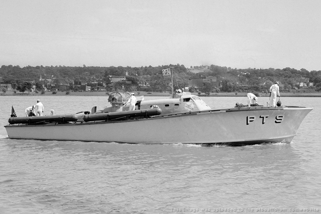
It was his belief that it would be a sea worthy fast motor boat which could be applied to war type uses. The design is discussed in detail in his two patents, which pretty much replicated by his PV70 boat. These patents can be easily found on the internet for the United States, Canada or even Great Britain. But, are included below:
Click on the links to download a copy of the patent:
[url]http://www.ptboatforum.com/HubertScott-Paine-001.pdf[/url]
[b]Reference:[/b] See Page 5 of the pdf, or actual page 2 of the text portion, at Line 20-Left
And an accompanied patent:
[url]http://www.ptboatforum.com/HubertScott-Paine-002.pdf[/url]
Although the Elco 70’s varies a little from the original PV70 design, (renumbered by the US Navy as PT 9) it is pretty much copied, except for the bridge and trunk cabin changes.
Photo of Elco’s first series of 70ft boats, PT 12.
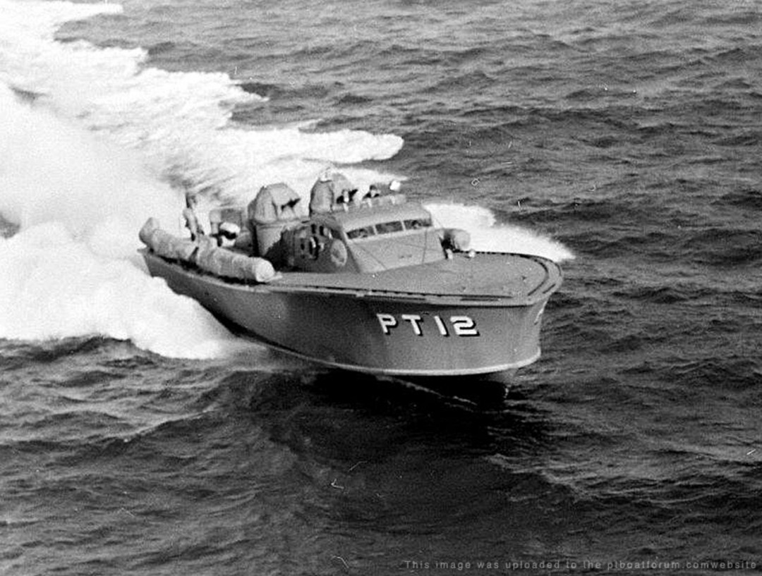
Along with the 70-foot boats, the Elco designs of the 77-foot and 80-foot boats appeared to keep the same style hull structure.
[b]Higgins Gun Turret Placement:[/b]
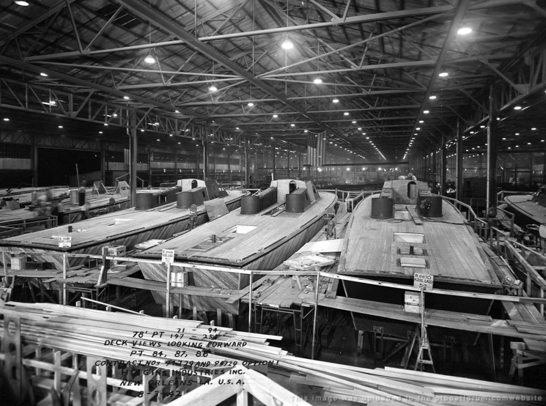
All three American motor torpedo boats designs were based on each companies own design philosophy and concepts for the boats. In some cases the Navy dictated some specific aspects. As is the case with Higgins. The first Higgins boats contracted were PT 71-94 and were being built as shown in the first two photos below:
Photo of early Higgins Design PT 80 launched.
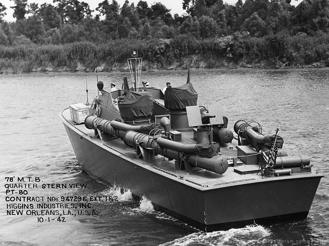
Photo of Higgins factory floor with first early design boats, PT 84, 87, 88.
[b][red]NO CORRECTION REQUIRED[/red][/b]
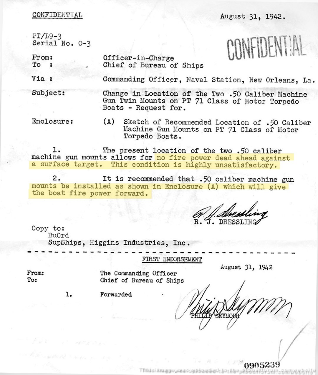
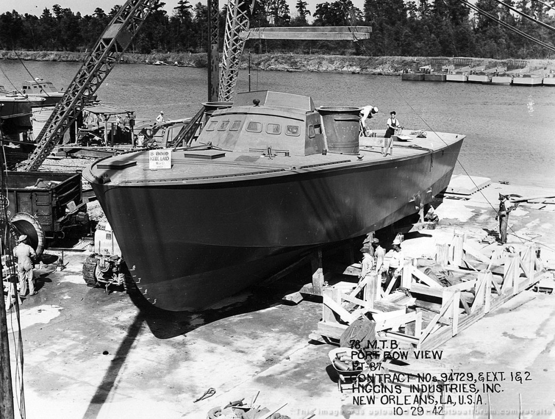
As can bee seen, the Higgins boats had long deck structures extending aft from the bridge. Located at the aft ends of these two structures were gun turrets. As seen, the turrets were offset and not aligned with each other. The starboard side turret was closer to the bridge than the turret on the port side. I have no knowledge why the turret were offset, maybe firing positions. Regardless, the Navy rejected the first boats delivered, because of this turret placement and there inability to fire forward on attack. Higgins was order to moved the turrets forward next to the bridge, and placed in alignment with each other. Also the removal of the extended structures. This can be seen in the photos of the documents below:
Photos of Higgins boat configuration change request,
Document page 1.
Document page 2.
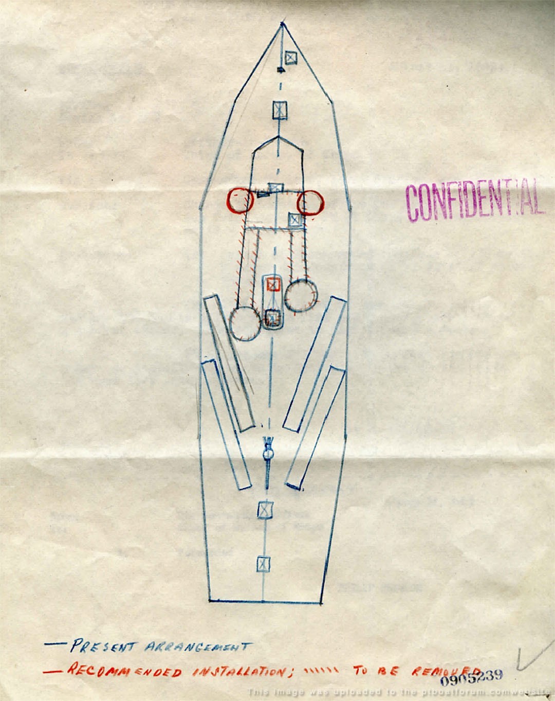
Photo of PT 87, boat launch with reconfigured design.
Thank you for the kind words about my cutaway artwork,
Dick . . .
Posted By: Dick | Posted on: Jun 21, 2021 - 4:01pm
Total Posts: 1489 | Joined: Aug 27, 2006 - 6:36pm
Dick, you will probably get a kick out of this, with machines designed with slide rules. Back in the late 80s, an airplane company called Christen noticed that the Piper Cub was about to celebrate its 50th anniversary. They thought, surely with modern computers they could do better! Every time they put in the paramotors for the new plane, the CAD would spit out the drawings for a Super Cub. People have tried the same thing with modern computers with the same results, a Super Cub, with all the later STOL mods developed in the 60s and 70s. Hard to beat perfection! I was trained to use slide rules as late as the mid 70s, need a backup for when your batteries fail on the calculator. I still pull them out to see what I still remember.
Posted By: Stearman | Posted on: Jun 21, 2021 - 9:00pm
Total Posts: 151 | Joined: Nov 1, 2017 - 9:38pm
For understanding the BPB and Elco hull design and construction I recommend three books. Race Against The Odds by Kevin Desmond, which covers the early BPB design influence of Fred Cooper. Fast Boats and Flying Boats by Adrian Rance which covers BPB, and last, the Bible of PT Boat design, Naval Architecture of Planing Hulls by Lindsay Lord.
As to initial .50 cal gun placement, BuShips heavily influenced the placement. I know they had Huckins move his turrets aft and inboard, he had them in similar configuration as used for PT-69. I believe they also did that with Higgins, although I don't have actual documentation on that one. Believe much of the gun placement had to do with the most stable location as an AA battery, and less to do with attacking surface vessels since the main weapon was suppose to be torpedoes and not short range guns.
Posted By: Andy Small | Posted on: Jun 22, 2021 - 5:26am
Total Posts: 267 | Joined: Nov 20, 2013 - 9:04pm
Stearman . . .
[b]Funny . . .[/b]
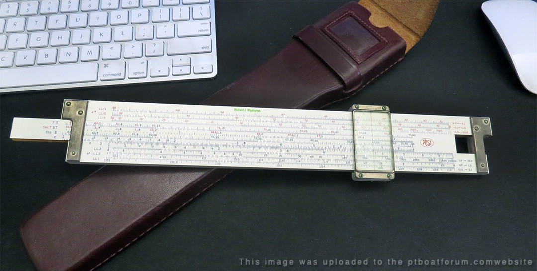
My slide rule antics go back to 1965 when all I could afford was one those $19 ABS plastic ones. These baby's were so inaccurate I was threatened by instructor that he would not give me a grade unless I got a real one! ! ! ! Later that year, and very fortunate for me, my brother-in-law to-be, who was attending Oregon State University and enrolled in their engineering program, decided he didn’t like engineering and changes his major. The fortunate part, was he gifted me his $140 solid bamboo professional, “Post,” slide rule. What a treasure for me, it would have been completely impossible for me to gather any similar amount even a much lessor amount of money for such a devise. I would now, probably get a grade from my Advance Analytical Math class.
Below, is my old trusty slide rule, I should say Tom’s (may he rest in peace) trusty slide rule. While looking at it today, I can barely read the scales, and 66 years later not sure what side or end to start on - oh how the brain goes when we get older.
Posted By: Dick | Posted on: Jun 22, 2021 - 2:06pm
Total Posts: 1489 | Joined: Aug 27, 2006 - 6:36pm
Andy . . .
I will look into the errors and correct the post as needed. I had sourced several well known books and a dozen or so internet articles on the matter and had assumed they were correct.
Thanks,
Dick . . . .
Posted By: Dick | Posted on: Jun 22, 2021 - 2:14pm
Total Posts: 1489 | Joined: Aug 27, 2006 - 6:36pm
Dick, that is a great story, sometimes we all get lucky. I pulled out one of my small slide rules, on the back it says, Keuffel & Esser Co. and in large letters, Beginner's Slide Rule! Oh well, it tot me the basic's.
Posted By: Stearman | Posted on: Jun 22, 2021 - 9:43pm
Total Posts: 151 | Joined: Nov 1, 2017 - 9:38pm
Hey Andy, good to hear from you! Thanks, I too thought that PV 70 was the future PT 9...
I had to buy one of those cheap plastic slide rules also Dick, for a HS math class. I don't remember ever using it in class, maybe the teacher's brother-in-law had a corner on the local slide rule market and teach was helping him out.
Posted By: Jeff D | Posted on: Jun 23, 2021 - 6:26am
Total Posts: 2203 | Joined: Dec 21, 2006 - 1:30am
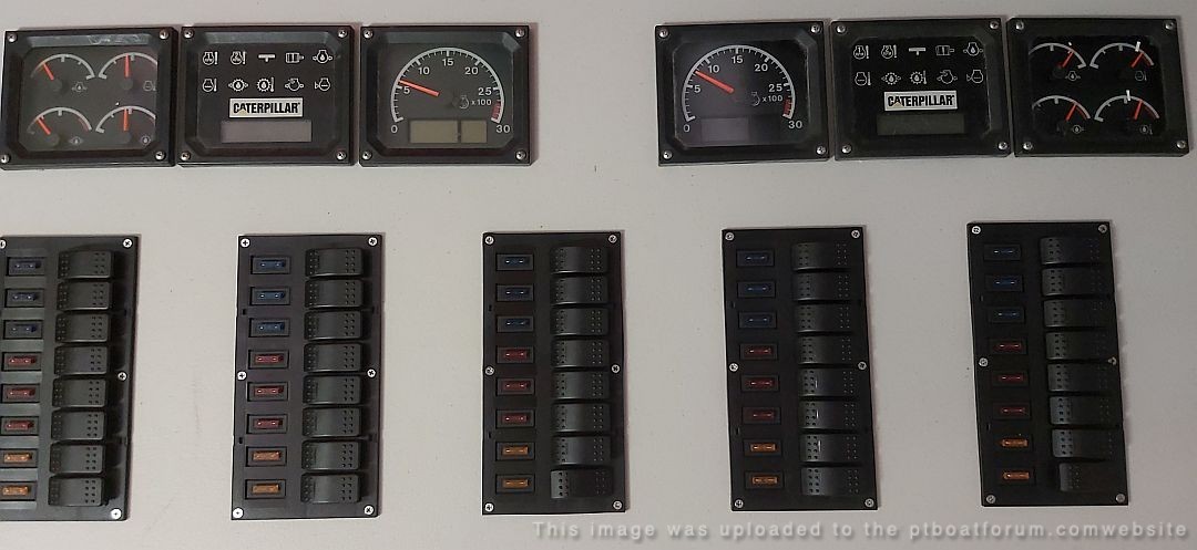
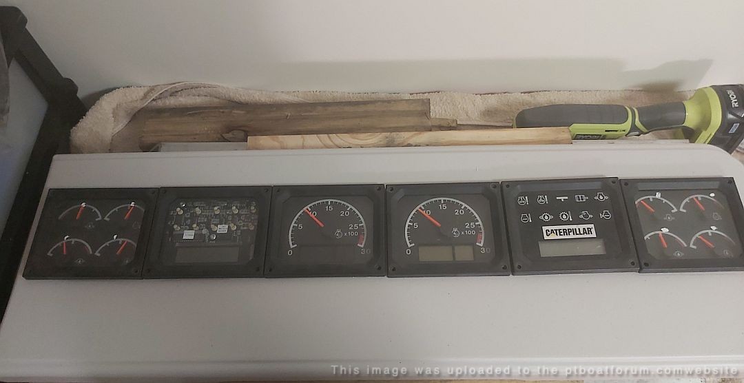
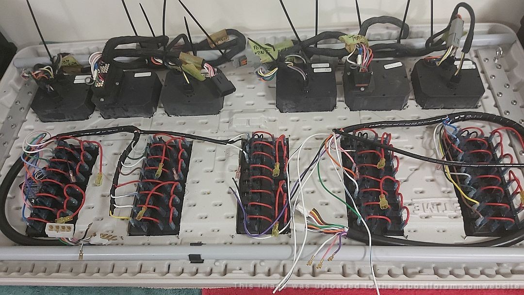
Paul sent an update, he's starting the mammoth task of wiring. I agree with him, Gulp!:
[green]
Just a quick update on the model boat project.
Late nite here in OZ.
Coffee.... CCR and Beach Boys blasting.
Working on SOME of the wiring looms.
80 foot boat looms make an F150 loom childs play.
These panels are for chartroom - engineer/motormac control.
A LOT more wiring to go!
Next month getting the 2 x Caterpillar V12, twin turbo engines shipped to Cat workshop for dyno tuning.
Wind 'em up .
Best have my plastic card at the ready for that.
Gulp!
[/green]
Posted By: Jeff D | Posted on: Apr 14, 2022 - 12:45pm
Total Posts: 2203 | Joined: Dec 21, 2006 - 1:30am
I forgot all about wiring! That was my specialty while working on the WWII aircraft. hopefully, he won't have to work on a 3" bundle of wire, where every wire is white!
Posted By: Stearman | Posted on: Apr 14, 2022 - 9:11pm
Total Posts: 151 | Joined: Nov 1, 2017 - 9:38pm
Hah Stearman, that would be a nightmare! Hard enough to figure out electrical problems without that.
Paul sent me some details of what the electrical systems involve, I'd say he has his work cut out for him!
[green]
As discussed, the wiring involved is a MISSION.
Over 40 separate electrical systems.
Bilge pumps
Navigation lites
Interior lites
VHF radios
Alarm systems
CCTV cameras
PA system
Audio system
Fuel pumps
Engine monitoring
Toilets
Potable water systems
Anchor winch
Laptop power
Cell phone power
Man overboard system
Ship / shore connections
Cordless tool recharging
Battery monitoring
Ships horn.
General Quarters siren
Marine AIS system
Weapons readiness system
Electric/ hydraulic rudder system
Black / gray water pumps
Radar
Depth sounder
Search lite.
The list goes on...... Of course, just imagine the actual amount and cost of hardware for every system !
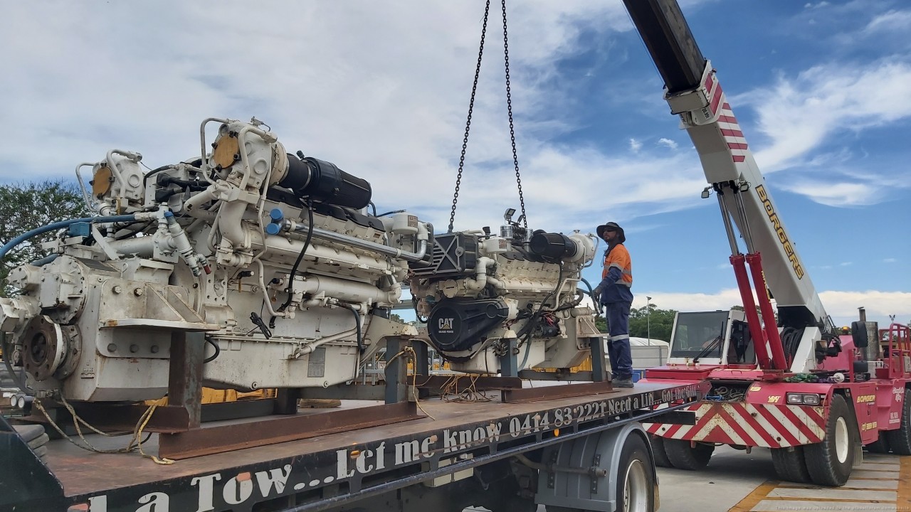
The 2 x Caterpillar 3412e twin turbo engines will be crane trucked to Caterpillar workshop for dyno testing prior to install ($$$$$)
With Twin Disc gearboxes.....3.5 tons each.
Covid restrictions in OZ completely gone now.
The economy is roaring..worlds best they tell me.
This makes skilled workers in very high demand.
This makes welding the hull later this year expensive.
VERY expensive.
Just have to pedal harder !
(easier said than done)
[/green]
Posted By: Jeff D | Posted on: Apr 15, 2022 - 7:01am
Total Posts: 2203 | Joined: Dec 21, 2006 - 1:30am
A quick update from Paul, he is still hard at work on the million and one smaller things that go into his project:
[green]
Hi Jeff,
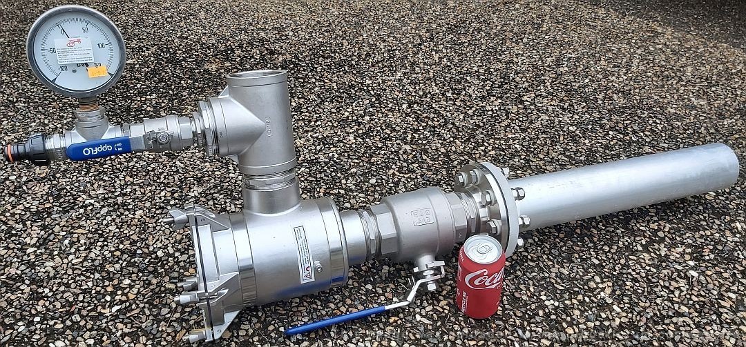
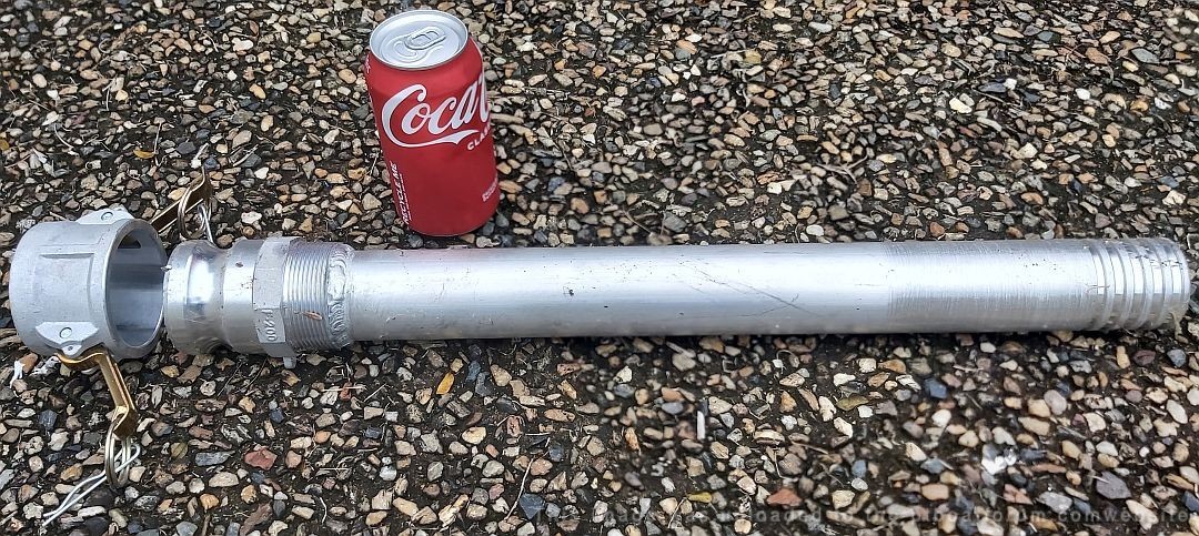
Restacking Project 109 components in storage shed.
One of the engine cooling water pick ups, with sea strainer and fresh water flush plumbing.
All 316 stainless, except electrically isolated aluminum pick up pipe.
Also, one of the many fuel fill pipes.
(4,000 liters capacity)
Cheers,
Paul.
(model boat builder, scale 1:1
[/green]
Posted By: Jeff D | Posted on: Aug 6, 2022 - 5:42am
Total Posts: 2203 | Joined: Dec 21, 2006 - 1:30am
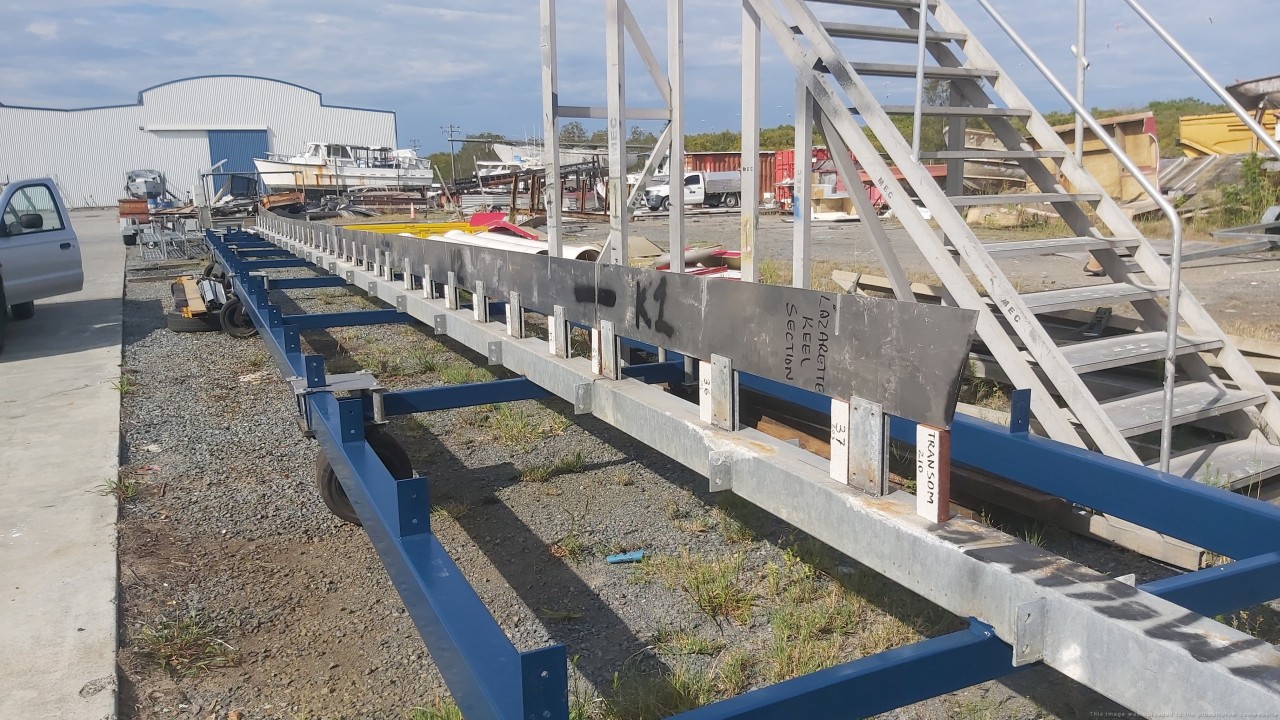
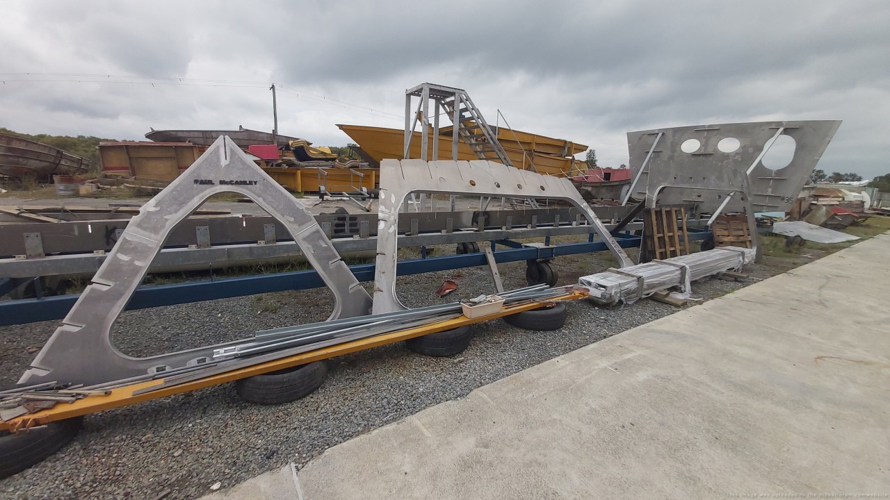
Paul has been busy, if nothing else proves how serious he is about his project then this major milestone will. After many months of prep work the hull is coming together, yay! From Paul:
[green]Hi Jeff.
Progress on Project PT109 continues.
A 'Woohoo' day this week.
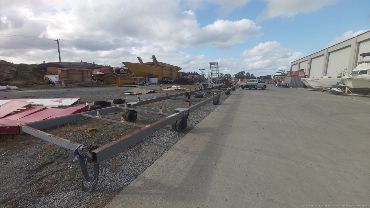
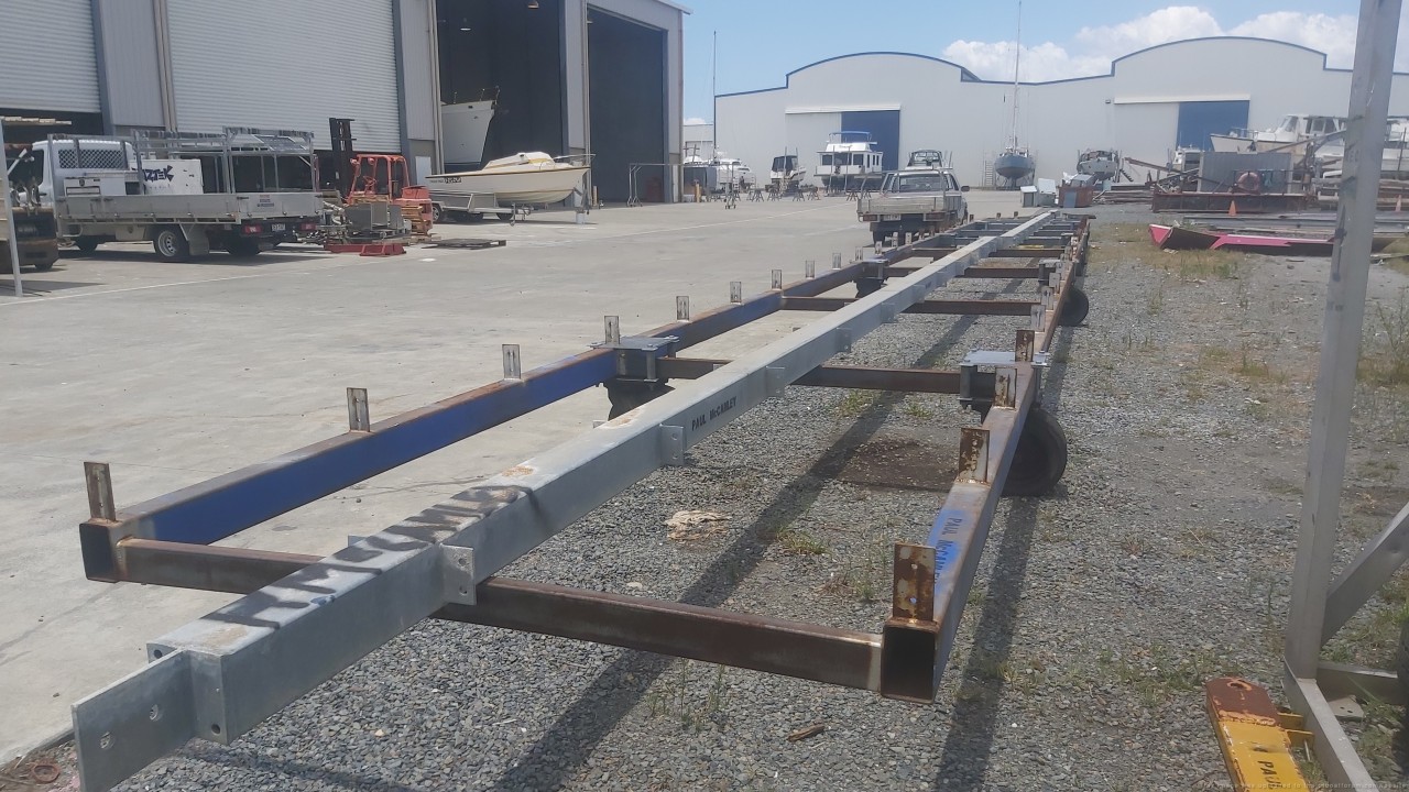
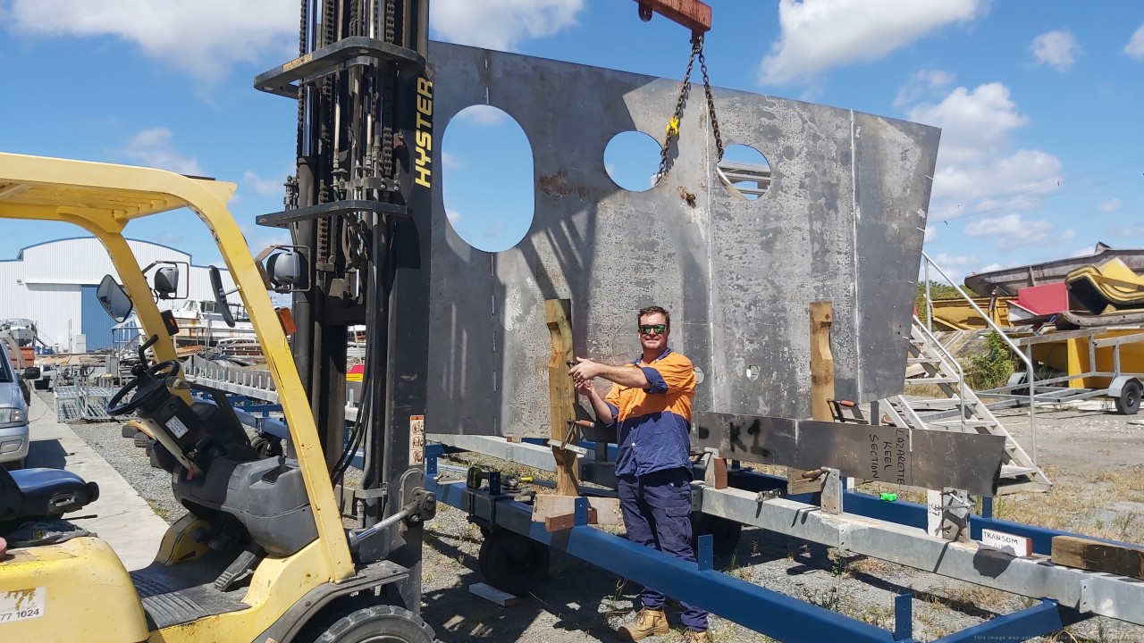
After completing the 80 foot hull build jig, first of 37 frames and bulkheads lowered into position.
This is the Lazarette bulkhead.
The 2 oval holes are for 254mm (10 inch ) stainless steel exhaust pipes to 6 x transom outlets.
The large oval hole on the left is dogged hatch.
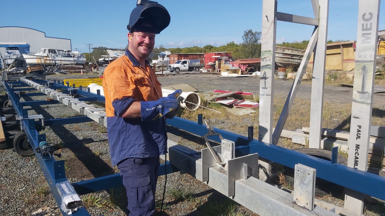
That is my buddy, Dan.
One of the best welders in OZ.
Lloyds and DNV accredited.
He builds Government and Police boats.
All his welds are x ray quality.
I am so lucky he helps me.
Build is outside in the hot Queensland sun, because budget doesn't allow a shed.
( I buy a LOT of sunscreen!)
I contacted Caroline Kennedy, US Ambassador to Australia for assistance from US Navy to advise best way to reach out to 350,000 US Navy personnel.
I received a reply from
Captain Kevin 'Q' Quarderer,
US Naval Attache Australia.
Sadly in the negative.
Jeff, if you have a plan to reach out to US Navy personnel, and PT Enthusiasts to assist in funding, I would be mighty glad to hear it.
I will keep on, keeping on.
Will send update photos.[/green]
Cheers,
Pauly.
( Caterpillar engines now at Caterpillar Service for dyno tuning)
Posted By: Jeff D | Posted on: Mar 13, 2023 - 4:18am
Total Posts: 2203 | Joined: Dec 21, 2006 - 1:30am
WOW! Words fail me! Cheers, Dennis
Posted By: Stearman | Posted on: Mar 13, 2023 - 7:45pm
Total Posts: 151 | Joined: Nov 1, 2017 - 9:38pm
Same here Dennis!
Pauly sent some more images:
[green]
Transom transported to build jig:
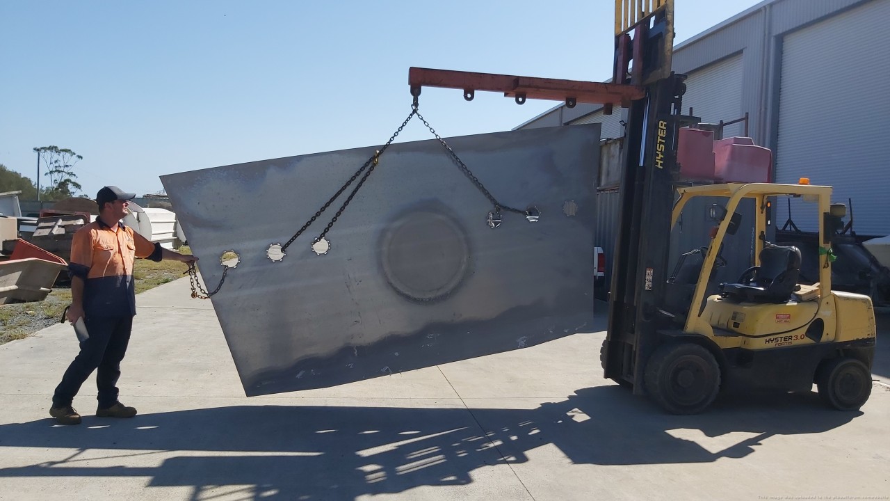
Stem positioning:

Stem stage 1 alignment:

Torpedo tubes in foreground:
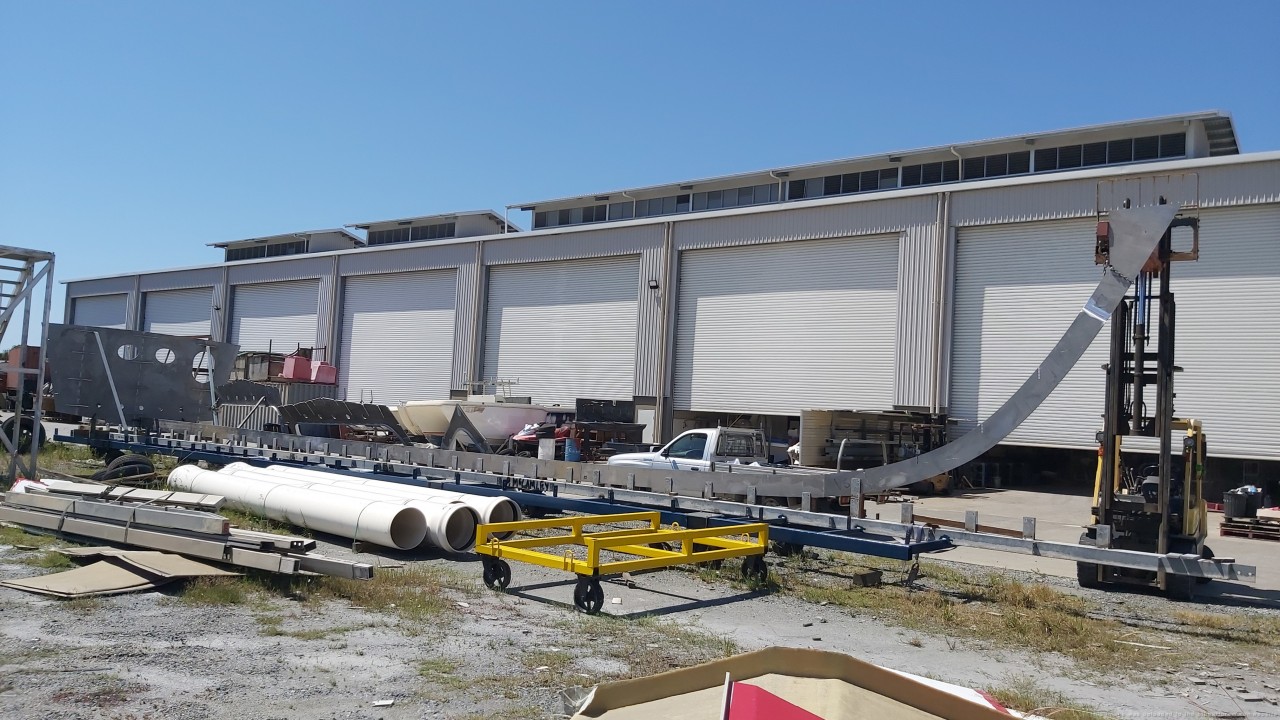
Quality of welds on the stem, note run on, run off bars:

33 degrees C today.
Hot work this model making!
More to follow.
Cheers,
Pauly.[/green]
Posted By: Jeff D | Posted on: Mar 18, 2023 - 12:47pm
Total Posts: 2203 | Joined: Dec 21, 2006 - 1:30am
I should have added, Dan's welding is first rate, a real work of art! Cheers, Dennis
Posted By: Stearman | Posted on: Mar 18, 2023 - 7:38pm
Total Posts: 151 | Joined: Nov 1, 2017 - 9:38pm
Paul sent some photos of his trial fitting the bow section, I love seeing her take shape!:
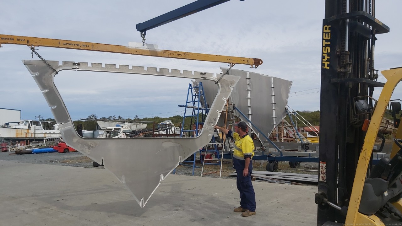
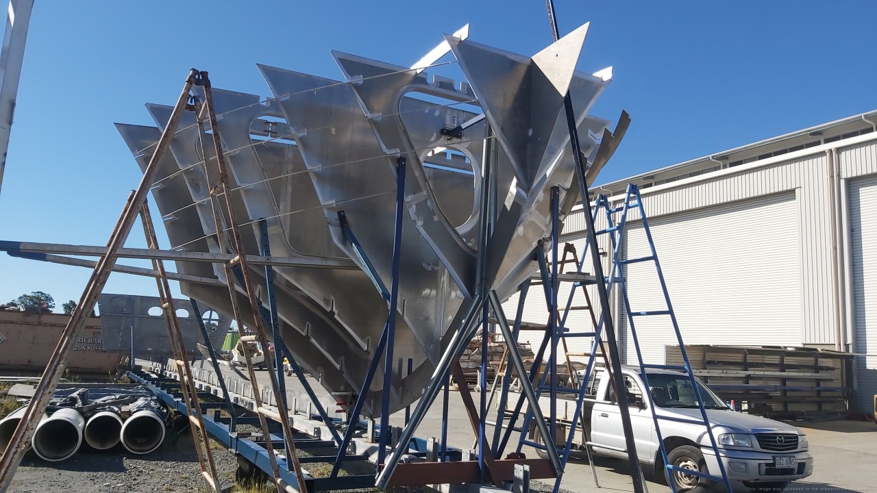
Posted By: Jeff D | Posted on: May 14, 2023 - 7:35am
Total Posts: 2203 | Joined: Dec 21, 2006 - 1:30am
A friend of Pauly's sent me an interesting article regarding Australian Coastwatcher Lieutenant Arthur “Reg” Evans, one of the men responsible for the rescue of the 109 crew after she got rammed by the Amagiri:
[url]https://www.awm.gov.au/articles/blog/coastwatcher-arthur-reginald-evans-and-the-rescue-of-john-f-kennedy-and-pt-109[/url]
Posted By: Jeff D | Posted on: Jun 12, 2023 - 5:34am
Total Posts: 2203 | Joined: Dec 21, 2006 - 1:30am
Pauly has a website up for Project PT 109:
[url]https://projectpt109.com/[/url]
If you can help with funding this awesome project, or help spread the word, he would sure appreciate it:
[url]https://gofund.me/b5cbf792[/url]
When I hit the Powerball tonight, Pauly's and FO's Elcos will be hitting the water in a few years.
Posted By: Jeff D | Posted on: Sep 9, 2023 - 11:47am
Total Posts: 2203 | Joined: Dec 21, 2006 - 1:30am
Pauly sent an update. If anyone has any ideas about other ways he can try to help with upcoming major costs like the hull plating and welding crew needed, he'd appreciate it.
[green]After spending thousands of dollars setting up website and Go Fund Me program..... NOT ONE THIN DIME ! Disappointing to say the least.
Never the less,
Work continues.
Current build stage.
Bulkhead #35, Frames 36 and 37, Transom.
Components.
2 x 750mm x 750mm rudders, rudderstocks and seals (316 SS)
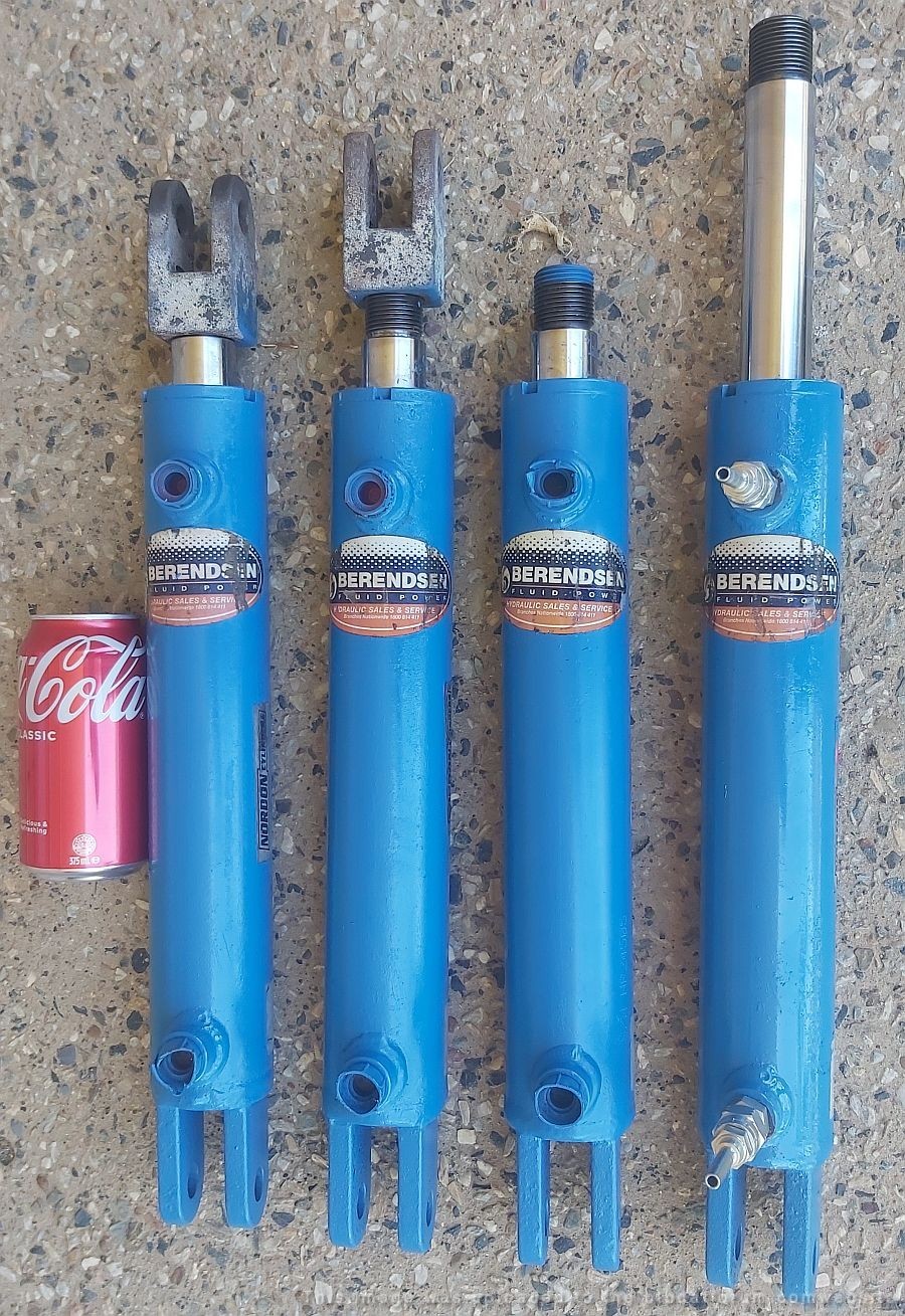
24v hi pressure power steering unit and wiring looms
Hi pressure hydraulic rams, hoses and fittings
Cadmium plated steel channel ram locators
Perimeter hull bracing for hydraulic system
Rudder tillers and cross links (316)
Exhaust-mufflers, outlet manifolds, (316), gaskets and isolators pads
Hull side scantlings and deck stiffeners
Main topside longtitudinal beams
(225mm x 100mm angle)
4 x engine girder extensions (16mm 5083)
4 additional longtitudinal members
$50 - $80k
ONE of the hydraulic ram locators:
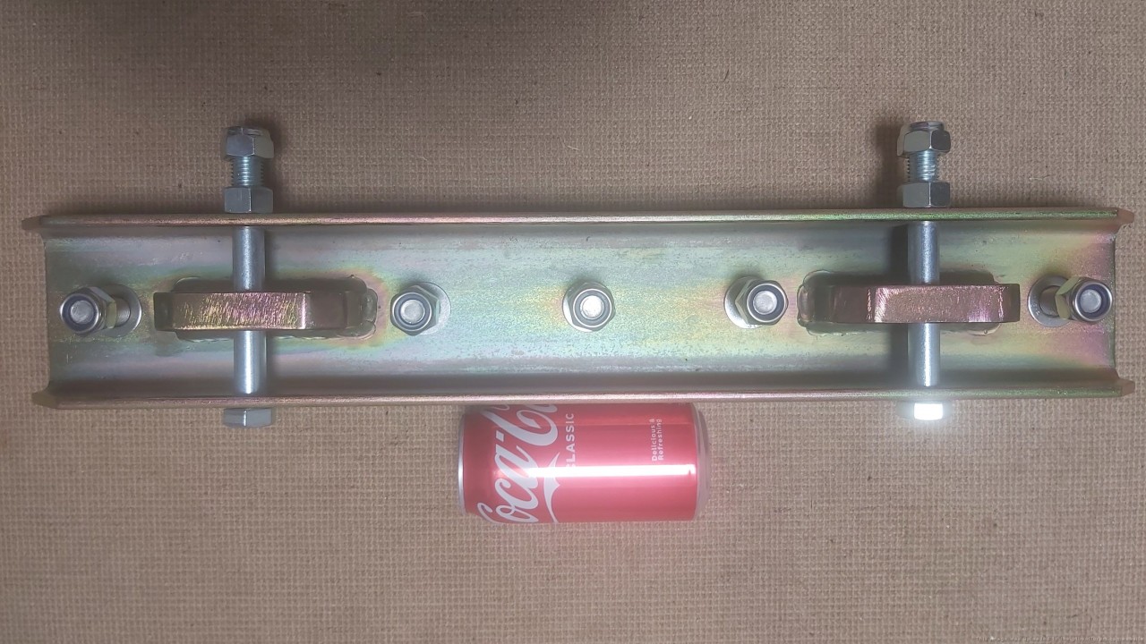
A high speed turn at 40+ knots on an 80 foot patrol boat requires literally tons of hydraulic rudder pressure.
The 4 rams:[/green]
Posted By: Jeff D | Posted on: Dec 10, 2023 - 8:20am
Total Posts: 2203 | Joined: Dec 21, 2006 - 1:30am
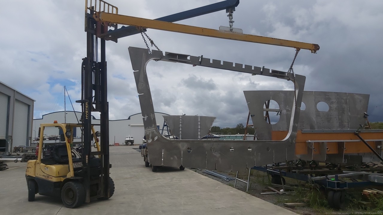
Pauly sent an update, the first is an aft frame:
Plus another interesting idea he has for funding:
[green]
Hi Jeff. Thank you for your assist so far.
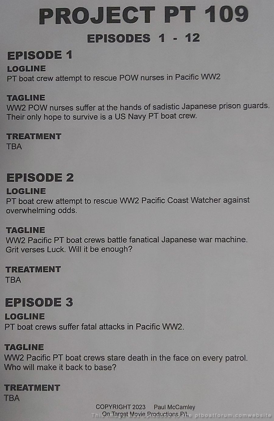
One possible funding option for the Project is a streaming deal, starring the PT boat.
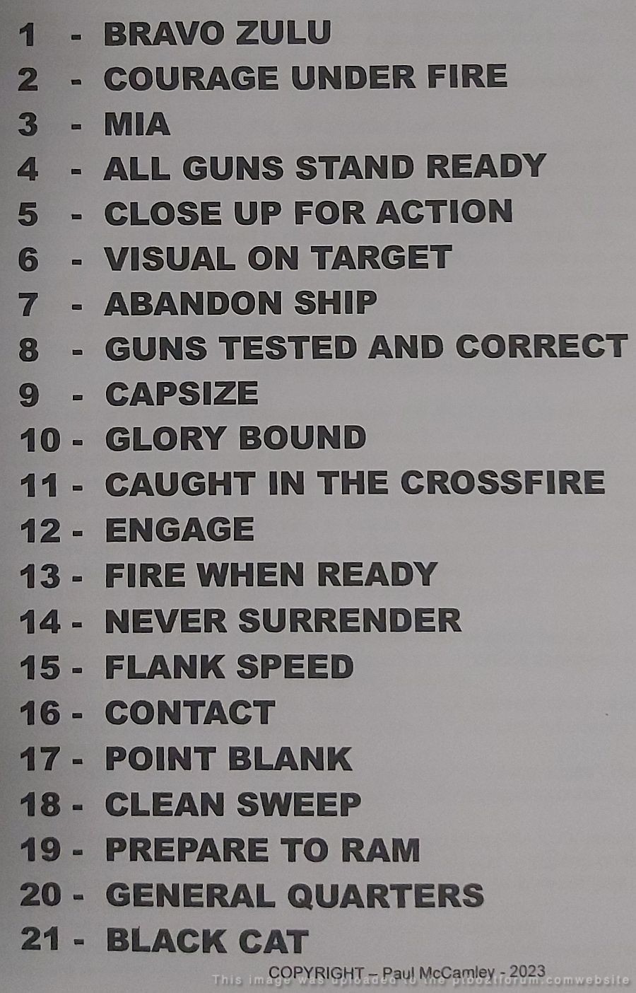
I have written a series of killer WW2 scripts (NOT referring to PT109).
Everyone who has read them says WOW.
Not your usual lame Disney/Hollywood sugar coated CGI stories.
No romantic subplots here.
Just brutal, graphic real events, as it happened.
These original scripts may interest streaming companies, or private investors seeking to enter the lucrative streaming market.
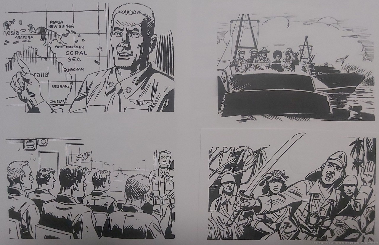
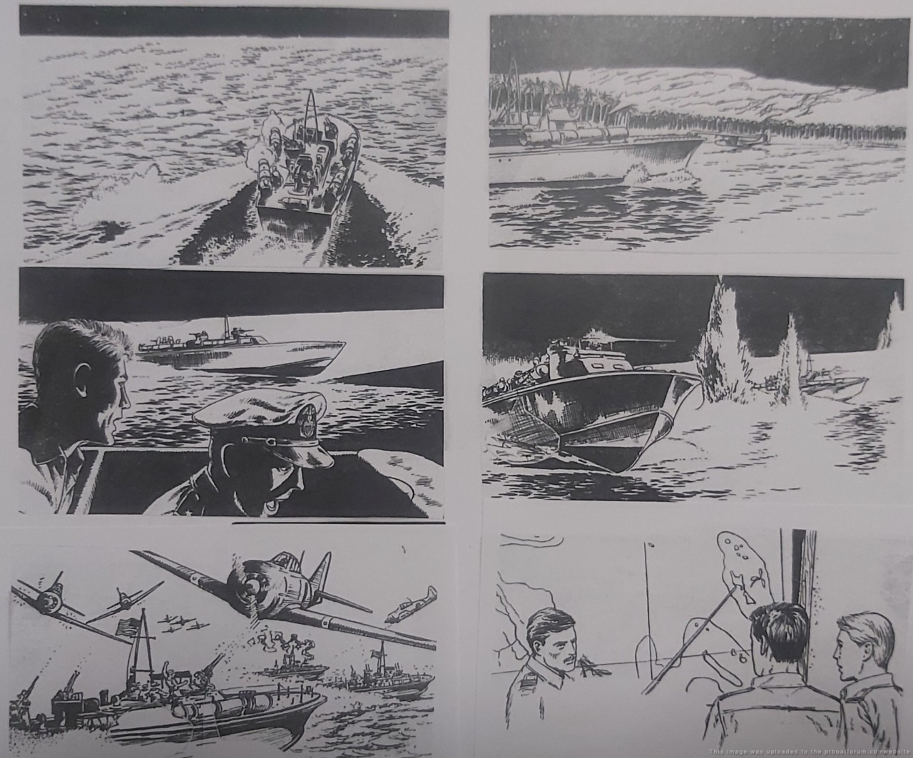
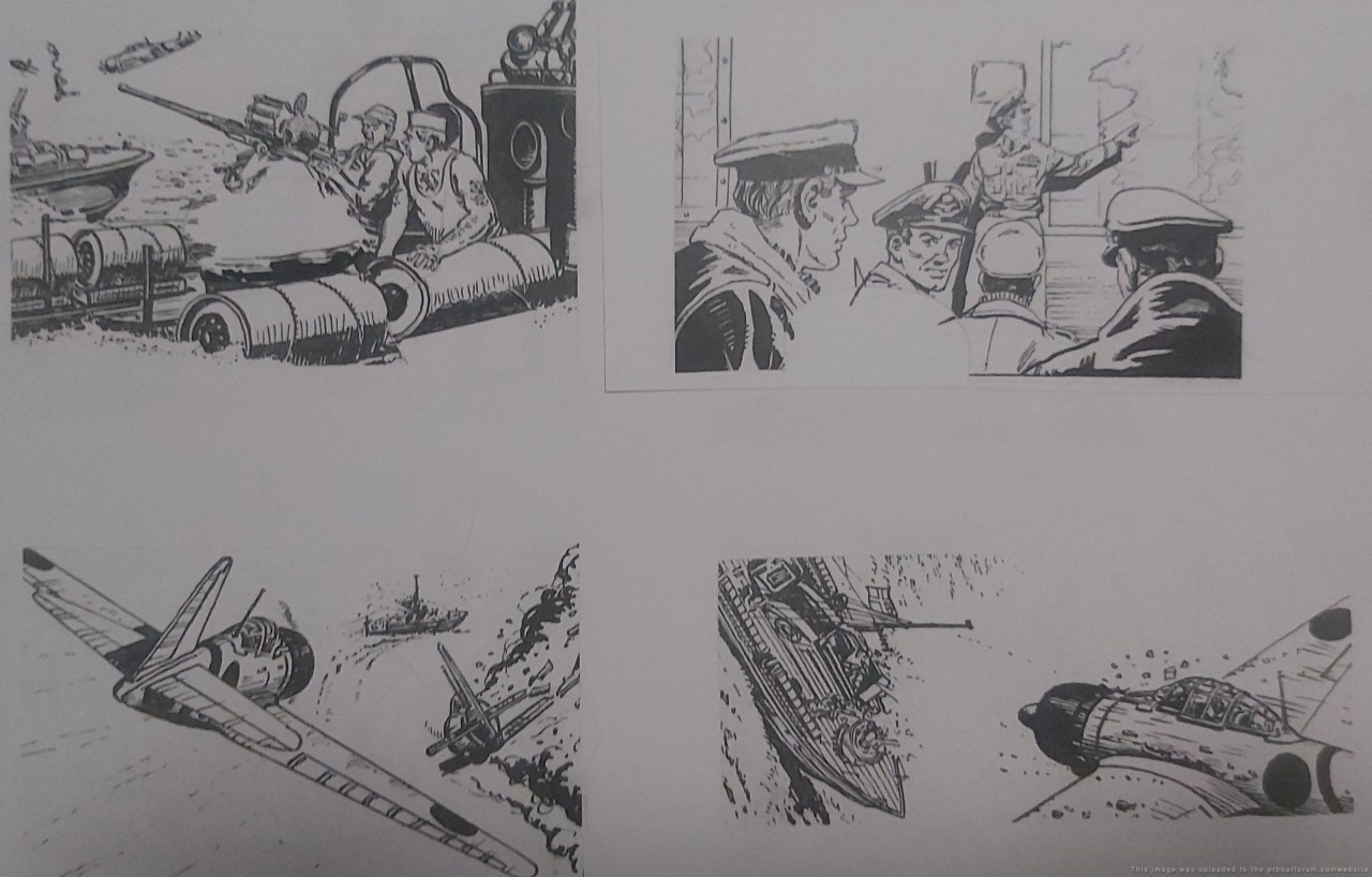
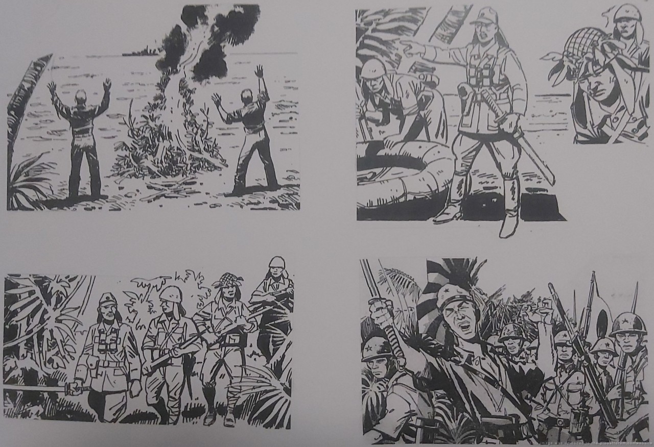
PT boats played a vital role in the WW2 victory in the Western Pacific.
If it wasn't for the bravery and sacrifices of the US military, I would be speaking Japanese.
Onwards.
Cheers,
Pauly.
[/green]
Good luck Pauly, I wish you good fortune!
Posted By: Jeff D | Posted on: Feb 6, 2024 - 1:57pm
Total Posts: 2203 | Joined: Dec 21, 2006 - 1:30am
An update from Pauly, the hull is coming along well! It sure is a lot more intricate than I imagined:
[green]Project PT109 progresses.
Finally leased a marina factory shed.
Leased a Toyota forklift.
(best in the business...made in USA apparently)
Check out the trial hull fit up.
That's the 40 foot bulkhead.
Only another 40 feet to go!
AFT section to be built first due to budget on factory size.
Fine alignment and welding to commence.
The engine girders in place.
Caterpillar V12 engines and Twin Disc gearboxes weigh 3.5 tons each.
Note circular sump access holes and riders.
Additional costs, but necessary in my ex mechanic experience.
Superstructure and MG turrets ready to fit up.
FWD section transported to factory shed area.
Still no Go Fund Me support received.
With 350,000 US navy personal, disappointing to say the least.
Onwards....
Cheers,
Pauly.[/green]


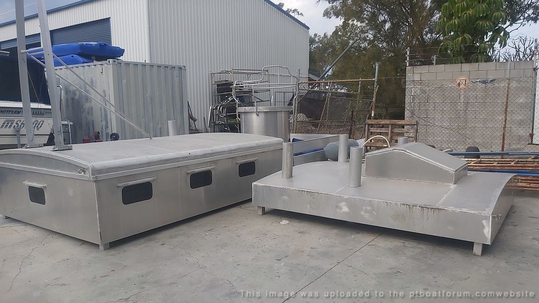
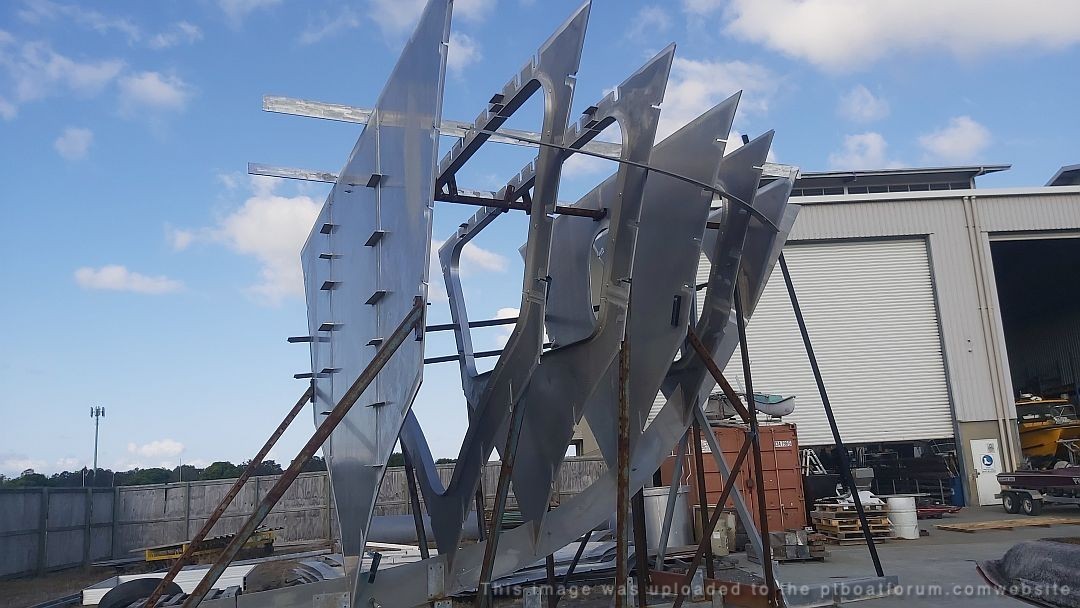
Posted By: Jeff D | Posted on: Sep 20, 2024 - 12:25pm
Total Posts: 2203 | Joined: Dec 21, 2006 - 1:30am
Thanks Jeff . . . .
Outstanding - I can't even imagine the costs. Way above my "pay-grade."
Its sad, 20, 25, or 30 years earlier, he would have had a lot of support. But the scare amount of remain vets, and their offsprings, the Splinters. As well the rest of us enuthuists are retired or at the very least nearly retirement are counting ever penny.
He's doing a great job and I wish him all the best in this adventure.
Dick . . .
Posted By: Dick | Posted on: Sep 21, 2024 - 12:16pm
Total Posts: 1489 | Joined: Aug 27, 2006 - 6:36pm
I clicked on the Go Fund Me site with intentions of making a donation but it states that the funding has been closed. Anybody have an ideas or info about that?
Harvey Wheeler
Posted By: Old LeadBottom | Posted on: Sep 26, 2024 - 3:53pm
Total Posts: 12 | Joined: Oct 4, 2013 - 7:36am
Hey Harvey, Pauly is looking into to this and thanks you in advance for any help!
Pauly sent another update:
[green]This model boat building is expensive but FUN!
Every day is fun.
Today I trial fitted the in hull walk ways.
Necessary to safely transit the vessel while underway in difficult conditions.
In additions to safe grip walk ways, hand grips/rails positioned for crew safety.
Mesh walkways necessary in engine area in case mechanics drop vital small parts.
Those scaffold planks ( $1,200) load bearing for AFT fuel tanks (2,000 liters)
These AFT tanks also require lateral bracing for beam on seas.
FWD tanks also 2,000 liters.
(positioned FWD for trim)
8,000 liter total capacity.
So FUN !
Lasers aid accurate build.
Of course not available to 1942 boat builders.
Necessary to align components to within 1-2 millimetres.
(the sheer cost of filling multiple 80 feet runs of 5mm welds with expensive 1.2 mig wire not an option)
Cheers,
Pauly[/green]


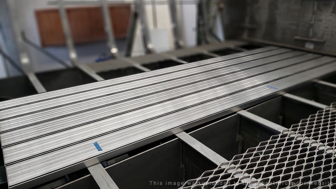

Posted By: Jeff D | Posted on: Sep 27, 2024 - 8:31am
Total Posts: 2203 | Joined: Dec 21, 2006 - 1:30am
An update from Pauly, step by step, inch by inch he's heading for the water:
[green]
Hull build is one thing, allowing for 1000 decisions of systems is additional.
One of 2 water pick ups/sea cocks.
Big dollar 316 items.
Electrically isolated and anode protected.
Guage is for freshwater pressure system flush at dock.
Deck cross brace square cutouts for over 1,000 feet of deck angle bracing.
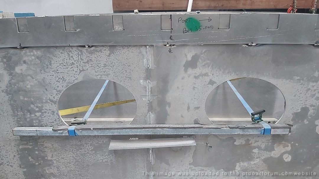
Check out the exhaust cut outs in bulkheads.
Large oval is dual exhausts thru, and 2 x ovals for exhausts to branch out Starboard and Port for 6 x transom outlets.
Rider bars being rolled for these cutouts.
No mufflers.
Sound like Thunder in the Alps at WOT.
Onwards...
Cheers,
Pauly.
[/green]

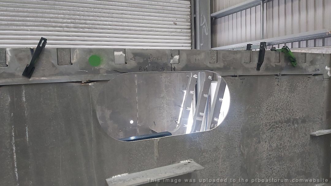
Posted By: Jeff D | Posted on: Oct 15, 2024 - 1:13pm
Total Posts: 2203 | Joined: Dec 21, 2006 - 1:30am


